۲۳. ماده پیزوالکتریک موجود در مبدل که امواج فراصوت تولید میکند، چه نام دارد؟
الف) ویفر کامپوزیت
ب) کریستال (یا المان پیزوالکتریک)
ج) دمپر (Backing)
د) عدسی صوتی
خودِ قطعهای که میلرزد و موج میسازد، همان کریستال یا المان پیزوالکتریک است.
۲۴. کدام مبدل دارای نازکترین کریستال پیزوالکتریک است؟
الف) مبدل ۱ مگاهرتز
ب) مبدل ۲.۲۵ مگاهرتز
ج) مبدل ۵ مگاهرتز
د) مبدل ۲۵ مگاهرتز
هرچه فرکانس بالاتر برود، ضخامت کریستال کمتر میشود (فرکانس با ضخامت نسبت عکس دارد).
۲۵. مقدار واگرایی پرتو (Beam Spread) عمدتاً به چه عواملی بستگی دارد؟
الف) فقط به ولتاژ دستگاه
ب) به فرکانس و اندازه کریستال
ج) به نوع مواد ضدصدا (Backing)
د) به زاویه ورود به قطعه
واگرایی با کاهش فرکانس و کوچکتر شدن کریستال افزایش مییابد.
۲۶. در یک قطعه با دانهبندی درشت (کریستالهای بزرگ)، چه پدیدهای رخ میدهد؟
الف) کاهش شدید امواج به دلیل پراکندگی (Scattering)
ب) افزایش سرعت صوت
ج) کاهش نویز پسزمینه
د) بهبود قدرت تفکیک
دانههای درشت باعث پراکندگی و تضعیف شدید امواج (Attenuation) و افزایش نویز روی صفحهنمایش میشوند.
۲۷. ساختار کریستالی در آلیاژها چه تأثیری در بازرسی فراصوت دارد؟
الف) فقط روی سرعت صوت تأثیر دارد
ب) باعث افزایش نویز (نویز متالورژیکی) و انتخاب فرکانس پایینتر میشود
ج) تأثیری در بازرسی ندارد
د) فقط روی کالیبراسیون تأثیر میگذارد
ساختار دانهبندی مستقیماً روی نویز پسزمینه و انتخاب فرکانس مناسب (معمولاً فرکانس پایینتر برای دانههای درشت) تأثیر دارد.
۲۸. پروب دوتایی (Twin Crystal) دقیقاً برای چه هدفی طراحی شده است؟
الف) افزایش قدرت نفوذ در فولاد
ب) کاهش منطقه مرده (Dead Zone) برای بازرسی قطعات نازک
ج) ایجاد امواج سطحی
د) افزایش زاویه پرتو
این پروب دو کریستال جداگانه دارد (یک فرستنده و یک گیرنده) که با زاویه قرار گرفتهاند تا ناحیه کور اولیه را به حداقل برسانند و عیوب نزدیک سطح را نشان دهند.
۲۹. کدام گزینه تأثیر مستقیم بر فرکانس طبیعی (رزونانس) یک کریستال دارد؟
الف) قطر کریستال
ب) ضخامت کریستال
ج) ولتاژ تحریک
د) جنس کابل پروب
۳۰. خاصیت پیزوالکتریک در کریستال به چه معناست؟
الف) تبدیل حرارت به صدا
ب) تبدیل فشار مکانیکی به ولتاژ و برعکس
ج) تولید مغناطیس در اثر جریان
د) عبور امواج نوری
۳۱. در پروب معمولی (تک کریستاله)، چه چیزی باعث میشود پالس ارسالشده کوتاه باشد و نوسان اضافه نداشته باشد؟
الف) ماده دمپر (Backing) با امپدانس بالا
ب) روکش محافظ (Wear plate)
ج) عدسی صوتی
د) اتصال زمین
دمپر پشت کریستال، نوسانات اضافی رو میگیره و باعث تولید پالس کوتاه با پهنای باند پهن میشه
۳۲. اگر دو کریستال با فرکانس یکسان ولی قطر متفاوت داشته باشیم، کدام یک میدان نزدیک (Near Field) بیشتری دارد؟
الف) کریستال با قطر بزرگتر
ب) کریستال با قطر کوچکتر
ج) هر دو برابرند
د) به جنس کریستال بستگی دارد
فرمول میدان نزدیک: N = D² / (4λ) ، هر چی قطر بیشتر، میدان نزدیک طولانیتر
۳۳. کریستال کامپوزیت (Composite) نسبت به کریستال سرامیکی معمولی چه مزیتی دارد؟
الف) ارزانتر است
ب) پهنای باند بیشتر و حساسیت بهتر دارد
ج) دوام بیشتری دارد
د) ولتاژ کمتری نیاز دارد
کامپوزیتها از ترکیب پلیمر و سرامیک ساخته میشن و پاسخ فرکانسی وسیعتری دارن)
۳۴. چرا در فرکانسهای بالا (مثلاً ۱۰ مگاهرتز) از کریستالهای با قطر کوچک استفاده میشود؟
الف) چون کریستال کوچک ارزانتر است
ب) برای جلوگیری از همهمپوشانی میدان نزدیک و دور
ج) چون دمپر کوچکتر نیاز دارد
د) برای افزایش ولتاژ خروجی
۳۵. کدام یک از موارد زیر باعث کاهش زاویه واگرایی (Beam Spread) میشود؟
الف) کاهش فرکانس
ب) کاهش قطر کریستال
ج) افزایش قطر کریستال
د) کاهش سرعت صوت در ماده
۳۶. یک پروب با قطر کریستال ۲۰ میلیمتر و فرکانس ۲ مگاهرتز، در فولاد (V=۵۹۰۰) چند درجه زاویه واگرایی (نیمزاویه) دارد؟
(فرمول: sinθ = ۱.۲۲ × (λ ÷ D))
الف) ۲۰ درجه
ب) ۱۵ درجه
ج) ۱۰ درجه
د) ۱۸ درجه
۳۷. در یک فرکانس ثابت، اگر قطر کریستال را افزایش دهیم، طول میدان نزدیک (Near Field) چه تغییری میکند؟
الف) کاهش مییابد
ب) افزایش مییابد
ج) ثابت میماند
د) به جنس ماده بستگی دارد
۳۸. کدام گزینه در مورد افزایش فرکانس درست است؟
الف) طول موج افزایش و قدرت تفکیک کاهش مییابد
ب) طول موج کاهش و قدرت تفکیک افزایش مییابد
ج) طول موج و قدرت تفکیک هر دو افزایش مییابند
د) تأثیری بر قدرت تفکیک ندارد
۳۹. در بازرسی یک قطعه نازک، چرا باید از پروبی با قطر کریستال کوچک استفاده کرد؟
الف) برای افزایش توان نفوذ
ب) برای کاهش طول میدان نزدیک و بازرسی در ناحیه دور
ج) برای افزایش ولتاژ خروجی
د) برای کاهش نویز
۴۰. برای بازرسی یک قطعه با ضخامت زیاد و دانهبندی ریز، بهترین انتخاب کدام است؟
الف) فرکانس پایین و قطر کوچک
ب) فرکانس بالا و قطر بزرگ
ج) فرکانس پایین و قطر بزرگ
د) فرکانس بالا و قطر کوچک
۴۱. کدام یک از موارد زیر اکوی پشت کار (Backwall Echo) را به شدت کاهش میدهد، ولی موج ارسالی را کاملاً قطع نمیکند؟
الف) حفره (Void) بزرگ در مسیر
ب) ترک عمودی با زاویه ۹۰ درجه نسبت به سطح
ج) تغییر ضخامت (Taper)
د) سطح ناهموار (Rough Surface)
۴۲. در بازرسی فراصوت، همگرایی (Convergence) باعث چه تغییری در دامنه اکو میشود؟
الف) کاهش دامنه به دلیل پراکندگی
ب) افزایش دامنه به دلیل متمرکز شدن امواج
ج) تأثیری در دامنه ندارد
د) باعث محو شدن اکو میشود
۴۳. اگر سطح پشت کار قطعه ناهموار یا کج (Skew) باشد، چه اتفاقی برای اکوی دریافتی میافتد؟
الف) دامنه اکو افزایش مییابد
ب) دامنه اکو کاهش مییابد (به دلیل بازتاب پراکنده)
ج) اکو به طور کامل حذف میشود
د) تغییری نمیکند
وقتی سطح پشت کار صاف و عمود بر پرتو نباشه، امواج به جای بازگشت به پروب، در جهات مختلف پراکنده (Scatter) میشن و دامنه اکوی دریافتی کم میشه.
۴۴. کدام یک از موارد زیر دلیل کاهش اکو نیست و نباید با عیب اشتباه گرفته شود؟
الف) وجود ترک
ب) تغییر ضخامت (Taper) ناگهانی
ج) حفره (Porosity)
د) سوراخ (Hole)
۴۵. در کدام ماده، به دلیل ساختار دانه بندی درشت، اکو بیشتر کاهش مییابد؟
الف) فولاد با دانهریز
ب) آلومینیوم
ج) چدن با گرافیت کروی
د) برنج
-- علت کاهش اکو توضیح
عیوب (ترک، حفره، سوراخ) بازتاب یا پراکندگی موج
-- سطح ناهموار (پشت کار یا ورودی) بازتاب پراکنده به جای بازتاب آیینه ای
-- دانه بندی درشت پراکندگی (Scattering) شدید
-- واگرایی پرتو (Beam Spread) اتلاف انرژی به خارج از مسیر
همگرایی (Convergence) افزایش اکو (نه کاهش!)
--تغییر ضخامت ناگهانی تغییر مسیر و کاهش اکو (عیب نیست)
--کوپلینگ نامناسب کاهش انتقال انرژی به قطعه
۴۶. در دستگاه فراصوت، گیت (Gate) چه وظیفه ای دارد؟
الف) تنظیم ولتاژ فرستنده
ب) تعیین محدوده زمانی برای مانیتورینگ سیگنال
ج) کنترل فرکانس مبدل
د) افزایش توان خروجی
۴۷. در صفحه نمایش A-Scan، محور افقی (X-Axis) نشاندهنده چیست و محور عمودی (Y-Axis) نشاندهنده چیست؟
الف) X: زمان یا عمق / Y: دامنه یا شدت سیگنال
ب) X: دامنه / Y: زمان
ج) X: ولتاژ / Y: فرکانس
د) X: فاصله از پروب / Y: دما
۴۸. در نمایش A-Scan، سیگنال اولیه سمت چپ صفحه (Initial Pulse یا زمان صفر) چه کاربردی دارد و چرا گاهی این سیگنال حذف (Suppress) میشود؟
الف) برای اندازه گیری عمق قطعه استفاده میشود و هرگز حذف نمیشود
ب) نشاندهنده لحظه ارسال پالس توسط کریستال است؛ حذف آن برای بزرگنمایی سیگنالهای نزدیک سطح
ج) نشاندهنده اکوی پشت کار است
د) برای کالیبره کردن دامنه استفاده میشود
۴۹. در دستگاه فراصوت، اگر دامنه سیگنال را ۶ دسیبل (dB) کاهش دهیم، دامنه ولتاژ آن چند برابر میشود؟
(فرمول: dB = 20 log(V1/V2))
الف) ۲ برابر
ب) نصف
ج) ۴ برابر
د) یکدهم
۵۰. در دستگاه فراصوت، کلید Reject (یا Suppression) چه تأثیری روی سیگنال دارد و چرا استفاده از آن در بازرسی استاندارد محدود شده است؟
الف) تمام سیگنالها را تقویت میکند
ب) سیگنال های با دامنه کمتر از آستانه مشخص را حذف (یا کاهش) میکند
ج) فقط سیگنال پشتکاره را حذف میکند
د) فرکانس دستگاه را تغییر میدهد
۵۱. در برخی دستگاهها، کنترل Damping (میرایی) وجود دارد که روی عملکرد Pulser تأثیر میگذارد. افزایش Damping چه اثری دارد؟
الف) طول پالس ارسالی را افزایش میدهد
ب) طول پالس ارسالی را کاهش میدهد و پهنای باند را افزایش میدهد
ج) دامنه پالس را افزایش میدهد
د) فرکانس مرکزی را تغییر میدهد
بالا یعنی پالس کوتاهتر و کریستال زودتر خاموش میشود. این کار قدرت تفکیک (Resolution) را بالا میبرد ولی حساسیت (Sensitivity) را کمی کاهش میدهد.
اگر در حین بازرسی، دامنه اکوی پشتکاره کاهش پیدا کند، اول باید کدام بخش دستگاه را بررسی کرد؟
جواب: ابتدا اتصال کابل و کاپلینگ، سپس تنظیمات Amplifier و Attenuator و در نهایت سلامت کریستال
۵۲. عوامل اصلی تضعیف امواج فراصوت در مواد، کدام گزینه است؟
الف) پراکندگی (Scattering) و جذب (Absorption)
ب) بازتاب (Reflection) و شکست (Refraction)
ج) همگرایی (Convergence) و واگرایی (Divergence)
د) تداخل (Interference) و پراش (Diffraction)
۵۳. در یک ماده مشخص، با افزایش فرکانس، ضریب تضعیف چه تغییری میکند؟
الف) کاهش مییابد
ب) افزایش مییابد
ج) ثابت میماند
د) به دما بستگی دارد
فرکانس بالاتر = تضعیف بیشتر = نفوذ کمتر. به همین دلیل در مواد دانهدرشت از فرکانس پایین استفاده میکنیم.
۵۴. در یک ماده با دانه بندی بسیار درشت، کدام پدیده بیشترین سهم را در تضعیف دارد؟
الف) جذب (Absorption)
ب) پراکندگی (Scattering)
ج) شکست (Refraction)
د) همگرایی (Convergence)
۵۵. کدام گزینه مهمترین مزیت روش تست غوطهوری (Immersion) نسبت به تست تماسی (Contact) است؟
الف) قیمت کمتر تجهیزات
ب) کوپلینگ یکنواخت و پایدار
ج) نیاز به نیروی کار کمتر
د) قابل حمل بودن دستگاه
۵۶. در تست غوطهوری، فاصله آبی (Water Path) باید به گونهای تنظیم شود که:
الف) اکوی BackWall در آب ظاهر شود
ب) اکوی سطحی (Interface Echo) قبل از ورود به قطعه قابل تشخیص باشد
ج) آب کاملاً حذف شود
د) پروب با قطعه تماس داشته باشد
فاصله آبی باید به اندازه ای باشد که پالس اولیه (Initial Pulse) از اکوی سطحی (Interface Echo) جدا شود و تداخل نکنند. همچنین باید به اندازه کافی باشد تا میدان نزدیک (Near Field) در آب کامل شود و موج به صورت صفحه ای (Plane Wave) به قطعه برخورد کند.
نکته: معمولاً فاصله آبی را حداقل ۲ تا ۳ برابر میدان نزدیک در آب در نظر میگیرند.
۵۷. در تست Immersion، اگر زاویه پروب نسبت به سطح قطعه تغییر کند، کدام پدیده رخ میدهد و چه تأثیری روی سیگنال دارد؟
الف) شکست (Refraction) و تغییر مسیر موج در قطعه
ب) افزایش دامنه اکو
ج) کاهش تضعیف
د) افزایش فرکانس
با تغییر زاویه پروب در آب، موج با زاویه مشخص به سطح قطعه برخورد کرده و بر اساس قانون اسنل (Snell’s Law) در قطعه شکست (Refraction) میخورد. این اصل برای تولید امواج عرضی (Shear Wave) در قطعه استفاده میشود.
نکته: زاویه بحرانی اول (Critical Angle) باعث تولید موج سطحی (Rayleigh) و زاویه بحرانی دوم باعث تولید موج عرضی خالص میشود.
۵۸. در تست غوطهوری، اگر آب داخل تانک حاوی حباب هوا باشد، چه اتفاقی میافتد؟
الف) دامنه اکو افزایش می یابد
ب) حبابها باعث پراکندگی و کاهش دامنه سیگنال میشوند
ج) فرکانس دستگاه تغییر میکند
د) پروب داغ میشود
حباب های هوا در آب، مانند مرز صوتی عمل کرده و بخشی از انرژی موج را پراکنده (Scatter) یا منعکس می کنند. این موضوع باعث کاهش شدید دامنه اکو و ایجاد نویزهای کاذب روی صفحه میشود.
نکته: برای جلوگیری از این مشکل، از آبزدایی (Deaeration) یا مواد ضدکف استفاده میشود.
۵۹. در تست غوطهوری، برای اینکه فقط سیگنالهای مربوط به قطعه را ببینیم و سیگنالهای ناشی از آب را حذف کنیم، از کدام قابلیت دستگاه استفاده میشود؟
الف) گیت (Gate) روی ناحیه قطعه
ب) افزایش ولتاژ Pulser
ج) کاهش بهره (Gain)
د) تغییر فرکانس
با تنظیم گیت (Gate) روی محدوده زمانی مربوط به داخل قطعه (بعد از اکوی سطحی)، میتوان سیگنال های آب (نویز) را نادیده گرفت و فقط اکوهای برگشتی از درون قطعه را مانیتور کرد.
نکته: همچنین از Delay برای عقب انداختن زمان شروع گیت استفاده میشود.
۶۰. در تست غوطهوری، اگر فاصله آبی (Water Path) برابر میدان نزدیک (Near Field) در آب باشد، چه تأثیری روی کیفیت بازرسی دارد؟
الف) بهترین حالت ممکن است
ب) موج در ناحیه نزدیک است و دامنه نوسانی دارد، بنابراین خطا ایجاد میشود
ج) هیچ تأثیری ندارد
د) فقط روی فرکانس تأثیر دارد
در میدان نزدیک، دامنه موج به شدت نوسان (نایکنواخت) دارد. اگر قطعه دقیقاً در این ناحیه قرار گیرد، دامنه اکوها به جابجایی های میلیمتری حساس شده و خطای اندازه گیری ایجاد میشود. بنابراین فاصله آبی باید بیشتر از میدان نزدیک باشد تا موج در ناحیه دور (Far Field) با دامنه یکنواخت به قطعه برخورد کند.
۶۱. اگر میزان Damping (میرایی) را افزایش دهیم، کدام یک از موارد زیر کاهش مییابد؟
الف) پهنای باند (Bandwidth)
ب) قدرت تفکیک (Resolution)
ج) حساسیت (Sensitivity)
د) طول پالس (Pulse Length)
افزایش Damping یعنی کریستال زودتر خاموش میشه و پالس ارسالی کوتاهتر میشه.
-پالس کوتاهتر = پهنای باند بیشتر و قدرت تفکیک بهتر (پس گزینه های الف و ب و د غلط هستن چون افزایش می یابند نه کاهش).
-ولی پالس کوتاهتر انرژی کمتری داره، در نتیجه حساسیت دستگاه (توانایی تشخیص عیوب ریز) کاهش پیدا میکنه.
۶۲. در تست زاوی هدار (Angle Beam) با یک پروب ثابت (مثلاً ۴۵ درجه)، اگر ماده مورد بازرسی از فولاد به آلومینیوم تغییر کند، زاویه موج در قطعه چه تغییری میکند؟
(سرعت طولی در فولاد ≈ ۵۹۰۰، در آلومینیوم ≈ ۶۳۰۰ متر بر ثانیه)
الف) افزایش می یابد
ب) کاهش می یابد
ج) ثابت میماند
د) به فرکانس بستگی دارد
بر اساس قانون اسنل:
(Sin θ₁ / V₁) = (Sin θ₂ / V₂)
با ثابت بودن زاویه در پروب (θ₁)، اگر سرعت در ماده جدید (V₂) بیشتر شود، سینوس زاویه در ماده (Sin θ₂) هم بیشتر میشود، یعنی زاویه موج در قطعه افزایش مییابد.
۶۳. در کالیبراسیون دستگاه UT به روش Distance-Amplitude Correction (DAC)، هدف اصلی چیست؟
الف) افزایش ولتاژ پالس
ب) جبران کاهش دامنه اکو به دلیل تضعیف و واگرایی با افزایش عمق
ج) تنظیم فرکانس دستگاه
د) حذف نویز پسزمینه
با افزایش عمق، دامنه اکوی یک عیب ثابت به دلیل تضعیف مواد و واگرایی پرتو کاهش مییابد. منحنی DAC این افت را جبران میکند تا عیوب با اندازه یکسان در هر عمقی، دامنه یکسانی روی صفحه نشان دهند. این کار با کشیدن منحنی از اکوهای پشت کار یا سوراخ های جانبی در عمق های مختلف انجام میشود.
-- Damping رو اینطوری به خاطر بسپار: Damping بالا = Resolution بالا ولی Sensitivity پایین
-- زاویه با تغییر ماده رو با قانون اسنل حل کن: هر چی سرعت ماده بیشتر، زاویه موج بازتر (بزرگتر)
-- DAC رو هیچوقت با TCG اشتباه نگیر! TCG همون کار رو به صورت زمانی (Time Corrected Gain) و خودکار انجام میده، ولی DAC به صورت منحنی دستی یا نیمه اتوماتیکه.
۶۴. مهمترین مزیت روش Through Transmission نسبت به روش Pulse-Echo چیست؟
الف) نیاز به کالیبراسیون ندارد
ب) تأثیر ناهمواری سطح کمتر است
ج) پروب ارزانتری نیاز دارد
د) عیوب را با دقت بیشتری عمقیابی میکند
در روش Through Transmission، دو پروب داریم: یکی فرستنده (کنار قطعه) و یکی گیرنده (سمت دیگر قطعه). موج از یک طرف فرستاده و از طرف دیگر دریافت میشود.
-- اگر سطح قطعه ناهموار باشد، فقط مسیر موج مختل میشود، ولی اکوی سطحی (Interface Echo) نداریم که تداخل ایجاد کند.
-- در روش Pulse-Echo، ناهمواری سطح باعث کاهش شدید اکوی BackWall و ایجاد خطا میشود.
نکته: این روش برای ورقهای نازک و مواد کامپوزیت هم عالی است
۶۵. کدام یک از موارد زیر مهمترین محدودیت روش Through Transmission است؟
الف) نیاز به دسترسی به دو طرف قطعه
ب) دقت کم در تشخیص عیوب کوچک
ج) نیاز به فرکانس بسیار بالا
د) عدم امکان استفاده در مواد فلزی
۶۶. در روش Through Transmission، اگر یک عیب (مثلاً ترک یا حفره) در مسیر پرتو قرار گیرد، چه تغییری در سیگنال دریافتی رخ میدهد؟
الف) دامنه سیگنال افزایش مییابد
ب) دامنه سیگنال کاهش مییابد
ج) زمان رسیدن سیگنال تغییر میکند
د) فرکانس سیگنال تغییر میکند
در این روش، نبود عیب = دریافت حداکثر دامنه (امواج بدون مانع به گیرنده میرسند).
وجود عیب = بخشی از انرژی موج منعکس، پراکنده یا جذب میشود و انرژی کمتری به گیرنده میرسد : دامنه سیگنال کاهش مییابد.
نکته طلایی: این روش، عمق عیب را نشان نمیدهد (فقط وجود یا عدم وجود عیب را در مسیر مشخص میکند) و برای اندازهگیری طولی عیب (مثل اسکن ورقها) کاربرد دارد.
۶۷. در روش Through Transmission، برای تشخیص عیب در یک ورق نازک آلومینیومی، کدام پارامتر را باید به دقت تنظیم کرد؟
الف) فاصله بین دو پروب
ب) هم محوری (Alignment) دقیق دو پروب
ج) دمای آب
د) زاویه پروب ها
۶۸. در روش Through Transmission، برای کالیبره کردن دستگاه و تنظیم حساسیت (Sensitivity)، معمولاً از چه نوع بلوک یا استانداردی استفاده میشود؟
الف) بلوک پلهای (Step Block)
ب) بلوک با سوراخ جانبی (Side-Drilled Hole - SDH)
ج) بلوک V1 یا V2
د) بلوک با شیار U-shaped
در Through Transmission، چون اکوی BackWall نداریم (پروب گیرنده در طرف دیگر است)، نمیتوانیم از اکوی BackWall برای کالیبره کردن استفاده کنیم.
-- به جای آن، از بلوک هایی با سوراخ جانبی (SDH) با قطر مشخص (مثلاً ۱.۵ یا ۳ میلیمتر) در عمق های مختلف استفاده میکنیم.
-- با قرار دادن بلوک بین دو پروب، سیگنال عبوری از سوراخ را اندازه گیری کرده و Gain را طوری تنظیم میکنیم که آن سوراخ با دامنه مشخص (مثلاً ۸۰٪) نشان داده شود.
-- سپس قطعه مورد نظر را با همان تنظیمات بازرسی میکنیم. هرگونه کاهش دامنه نسبت به حالت کالیبراسیون، نشاندهنده وجود عیب است.
چرا در Through Transmission از بلوک پلهای (Step Block) برای کالیبراسیون عمق استفاده نمیکنیم؟
جواب: چون در این روش، زمان (Time Base) اهمیت چندانی ندارد (فقط دامنه سیگنال مهم است). Step Block بیشتر برای کالیبره کردن عمق (محور افقی) در روش Pulse-Echo کاربرد دارد.
۶۹. پس از رسم منحنی DAC، اگر در حین بازرسی، اکوی یک عیب از منحنی DAC بالاتر باشد، چه نتیجه گیری میکنیم؟
الف) عیب از عیب مرجع بزرگتر است
ب) عیب از عیب مرجع کوچکتر است
ج) عیب در عمق کمتر از حد انتظار است
د) دستگاه کالیبراسیون نشده است
۷۰. تفاوت اصلی بین DAC و TCG (Time Corrected Gain) چیست؟
الف) DAC دستی است، TCG خودکار
ب) DAC برای مواد فلزی است، TCG برای غیرفلزی
ج) TCG فقط برای Angle Beam کاربرد دارد
د) هیچ تفاوتی ندارند
۷۱. کدام گزینه تفاوت اصلی بین TCG و DAC را بهدرستی بیان میکند؟
الف) TCG برای مواد غیرفلزی و DAC برای مواد فلزی کاربرد دارد
ب) در TCG، ب (Gain) بهصورت خودکار و پیوسته با عمق تغییر میکند، ولی در DAC بهصورت دستی و با منحنی مرجع است
ج) TCG فقط برای پروبهای زاویهدار کاربرد دارد
د) TCG نیاز به بلوک کالیبراسیون ندارد
۷۲. برای کالیبره کردن TCG در یک دستگاه UT، معمولاً از چه روشی استفاده میشود؟
الف) استفاده از بلوک پلهای (Step Wedge) با اکوهای پلهها
ب) استفاده از بلوک با ضخامتهای مختلف و تنظیم Gain روی اکوی BackWall در هر عمق
ج) استفاده از بلوک V1 با شیارهای U-shaped
د) استفاده از بلوک با سوراخهای مخروطی
۷۳. در چه شرایطی استفاده از TCG به DAC ارجحیت دارد؟
الف) وقتی قطعه بسیار نازک است
ب) وقتی محدوده عمق بازرسی زیاد است و نیاز به دقت بالا در تمام عمقها داریم
ج) وقتی مواد دانهدرشت هستند
د) وقتی فقط یک عمق مشخص مدنظر است
-- اگر سوال پرسید «کدام روش برای جبران تضعیف در عمقهای مختلف مناسبتر است؟» جواب: هر دو (چون هر دو همین کار را میکنند).
-- اگر پرسید «تفاوت اصلی چیست؟» جواب: TCG خودکار و پیوسته است، DAC دستی و نقطهای.
-- اگر پرسید «برای کالیبره کردن TCG از چه بلوکی استفاده میشود؟» جواب: بلوک پلهای (Step Block) یا بلوک با سوراخهای جانبی در عمقهای مختلف.
-- اگر پرسید «کدام یک دقیقتر است؟» جواب: TCG (چون تغییرات Gain را پیوسته و خطی اعمال میکند).
۷۴. در بازرسی فراصوت، امواج طولی (Longitudinal Waves) در کدام محیطها منتشر میشوند؟
الف) فقط در جامدات
ب) فقط در مایعات
ج) فقط در گازها
د) در جامدات، مایعات و گازها
۷۵. کدام یک از موارد زیر نسبت به طول موج تأثیری بر حداکثر اندازه عیب قابل تشخیص ندارد؟
الف) فرکانس پروب
ب) سرعت صوت در ماده
ج) دامنه سیگنال (Amplitude)
د) اندازه کریستال
حداکثر اندازه عیب قابل تشخیص به طول موج بستگی دارد (λ = V/f). دامنه سیگنال فقط روی شدت اکو تأثیر دارد، نه روی حد تشخیص.
۷۶. در تست زاویهدار (Angle Beam)، برای تولید موج عرضی خالص در فولاد، زاویه ورود به قطعه باید بین چه مقادیری باشد؟
الف) کمتر از زاویه بحرانی اول
ب) بین زاویه بحرانی اول و دوم
ج) بیشتر از زاویه بحرانی دوم
د) دقیقاً برابر زاویه بحرانی اول
۷۷. کدام پدیده در مرز بین دو ماده با امپدانس آکوستیکی متفاوت رخ میدهد و باعث بازگشت بخشی از انرژی موج میشود؟
الف) بازتاب (Reflection)
ب) شکست (Refraction)
ج) پراکندگی (Scattering)
د) جذب (Absorption)
۷۸. برای بازرسی یک قطعه فولادی با ضخامت ۱۵۰ میلیمتر و دانهبندی نسبتاً درشت، کدام فرکانس مناسبتر است؟
الف) ۱۰ مگاهرتز
ب) ۵ مگاهرتز
ج) ۲ مگاهرتز
د) ۱۵ مگاهرتز
-- ضخامت زیاد > نیاز به نفوذ بالا > فرکانس پایینتر (تضعیف کمتر)
-- دانهدرشت > فرکانس پایینتر (پراکندگی کمتر)
-- فرکانس ۲ مگاهرتز بهترین تعادل بین نفوذ و قدرت تفکیک برای این شرایط است.
۱ . جامدات، مایعات و گازها امواج طولی در همه محیطها منتشر میشوند
۲ . دامنه سیگنال حد تشخیص عیب به طول موج وابسته است، نه دامنه
۳ . بین بحرانی اول و دوم شرط تولید موج عرضی خالص
۴ . بازتاب (Reflection) ناشی از اختلاف امپدانس آکوستیکی
۵ . ۲ مگاهرتز برای ضخامت زیاد و دانهدرشت
۷۹. کدام یک از امواج فراصوت در ورقههای نازک (کمتر از طول موج) منتشر میشود و به ضخامت و فرکانس وابسته است؟
الف) امواج طولی
ب) امواج عرضی
ج) امواج لمب (Lamb Waves)
د) امواج سطحی (Rayleigh)
۸۰. در مرز بین دو ماده با امپدانس آکوستیکی بسیار نزدیک (مثلاً فولاد و فولاد)، ضریب بازتاب (Reflection Coefficient) تقریباً چقدر است؟
الف) ۱ (۱۰۰٪ بازتاب)
ب) ۰ (تقریباً بدون بازتاب)
ج) ۰.۵
د) به فرکانس بستگی دارد
۸۱. در روش DAC، برای رسم منحنی در عمقهای مختلف، اگر از سوراخ جانبی (SDH) استفاده کنیم، دامنه اکوی دریافتی با افزایش عمق چگونه تغییر میکند؟
الف) افزایش مییابد
ب) کاهش مییابد (به دلیل تضعیف و واگرایی)
ج) ثابت میماند
د) به قطر سوراخ بستگی دارد
با افزایش عمق، به دلیل تضعیف مواد و واگرایی پرتو، دامنه اکوی یک سوراخ با اندازه ثابت کاهش مییابد. منحنی DAC دقیقاً این کاهش را جبران میکند.
۸۲. در تست زاویهدار، اگر زاویه پروب را از ۴۵ درجه به ۶۰ درجه افزایش دهیم (در فولاد)، عمق نقطه بازرسی برای یک مسافت ثابت (Skip Distance) چگونه تغییر میکند؟
الف) افزایش مییابد
ب) کاهش مییابد
ج) ثابت میماند
د) به فرکانس بستگی دارد
عمق = مسافت × tan(زاویه). با افزایش زاویه، tan زاویه افزایش مییابد، بنابراین برای یک مسافت ثابت، عمق کمتر میشود (نقطه بازرسی به سطح نزدیکتر میشود).
۸۳. در یک کریستال با قطر ۲۰ میلیمتر و فرکانس ۴ مگاهرتز در فولاد (V=۵۹۰۰)، میدان نزدیک چند میلیمتر است؟
(فرمول: N = D² ÷ (4λ))
الف) حدود ۲۰ میلیمتر
ب) حدود ۶۸ میلیمتر
ج) حدود ۱۳۶ میلیمتر
د) حدود ۳۴ میلیمتر
۸۴. در روش DAC، اگر یک عیب در عمق ۵۰ میلیمتری، دامن های برابر با DAC + 4 dB داشته باشد، نسبت به عیب مرجع چه نتیجهای میگیریم؟
الف) عیب کوچکتر از مرجع است
ب) عیب بزرگتر از مرجع است
ج) عیب هماندازه مرجع است
د) عیب در جهت نامناسب است
هرچه دامنه بالاتر از منحنی DAC باشد، عیب بازتابندهتر (معمولاً بزرگتر) است. ۴ دسیبل بالاتر یعنی حدود ۱.۶ برابر دامنه بیشتر.
۸۵. در روش Through Transmission، اگر یک عیب کوچک در مسیر پرتو قرار گیرد، کدام پارامتر به عنوان نشانه عیب ثبت میشود؟
الف) افزایش دامنه سیگنال
ب) کاهش دامنه سیگنال
ج) تغییر زمان رسیدن
د) تغییر فرکانس
عیب باعث کاهش انرژی رسیده به گیرنده میشود. این کاهش دامنه، نشانه وجود عیب است.
۸۶. برای بازرسی یک قطعه با سطح بسیار ناهموار و دسترسی فقط از یک طرف، کدام روش یا پروب مناسبتر است؟
الف) Through Transmission
ب) پروب دوکریستاله (Twin Crystal)
ج) پروب تککریستاله با دمپر بالا
د) تست با امواج سطحی
پروب دوکریستاله (با زاویهدار بودن کریستالها) ناحیه مرده (Dead Zone) را کاهش میدهد و برای سطوح ناهموار و قطعات نازک عالی است.
۸۷. اگر موجی از آب (V=۱۴۸۰) به فولاد (V=۵۹۰۰) با زاویه ۲۰ درجه وارد شود، زاویه شکست در فولاد چقدر است؟
(قانون اسنل: Sin θ₁/V₁ = Sin θ₂/V₂)
الف) حدود ۲۵ درجه
ب) حدود ۴۳ درجه
ج) حدود ۶۰ درجه
د) حدود ۹۰ درجه
۸۸. با افزایش دما در یک ماده جامد، سرعت انتشار امواج فراصوت معمولاً کاهش مییابد. در این صورت، اگر فرکانس ثابت بماند، کدام پارامتر تغییر میکند؟
الف) دامنه (Amplitude)
ب) طول موج (Wavelength)
ج) امپدانس آکوستیکی
د) تضعیف (Attenuation)
۸۹. در تست زاویه دار (Angle Beam)، اگر یک موج طولی از یک محیط با سرعت کمتر (مثل پلکسی گلاس پروب) به محیطی با سرعت بیشتر (مثل فولاد) وارد شود، چه تغییری در فرکانس موج رخ میدهد؟
الف) افزایش مییابد
ب) کاهش مییابد
ج) ثابت میماند
د) به زاویه ورود بستگی دارد
۹۰.در یک ماده با ویسکوزیته (گرانروی) بالا، امواج فراصوت به شدت مستهلک میشوند. در این شرایط، کدام ویژگی موج بدون تغییر باقی میماند؟
الف) دامنه (Amplitude)
ب) شدت (Intensity)
ج) فرکانس (Frequency)
د) سرعت ذرهای (Particle Velocity)
۹۱. اگر قطر یک کریستال را افزایش دهیم و فرکانس را ثابت نگه داریم، کدام پارامتر کاهش مییابد؟
الف) طول میدان نزدیک (Near Field)
ب) زاویه واگرایی (Beam Spread)
ج) طول موج
د) قدرت تفکیک (Resolution)
۹۲. امپدانس آکوستیکی یک ماده، برابر حاصلضرب کدام دو پارامتر است؟
الف) سرعت و فرکانس
ب) چگالی و سرعت صوت (Z = ρ × V)
ج) چگالی و فرکانس
د) سرعت و طول موج
۹۳. هنگام تست یک قطعه فولادی با پروب مستقیم (Straight Beam) با فرکانس ۵ مگاهرتز، اکو یا پژواک عیوب نزدیک به سطح (زیر ۳ میلیمتر) در صفحه نمایش قابل تفکیک از پالس اولیه نیست. مشکل اصلی کدام است؟
الف) فرکانس پروب برای این ضخامت بسیار کم است.
ب) عیب در "ناحیه مرده" (Dead Zone) پروب قرار دارد.
ج) کوپلانت بیش از حد غلیظ است.
د) دمپر پروب خراب شده است.
ناحیه مرده، فاصلهایست بلافاصله زیر سطح تماس که کریستال هنوز در حال ارتعاش (Ringing) است و قادر به دریافت اکوی برگشتی نیست. تا زمانی که ارتعاش کریستال میرا نشود، پالس ورودی دستگاه را کور میکند. افزایش فرکانس و استفاده از پروبهای Delay Tip یا Immersion راه حل آن است.
۹۴. فرمول محاسبه طول میدان نزدیک (Near Field) برای یک پروب دایرهای شکل چیست و چرا این ناحیه برای بازرسی حیاتی است؟
الف) N = D².f / 4.V — و برای محاسبه زاویه شکست به کار میرود.
ب) N = D² / 4.λ — و در این ناحیه دامنه اکو به شدت نوسان میکند و غیرقابل پیشبینی است.
ج) N = V / f — و برای تعیین فاصله بحرانی پروب استفاده میشود.
د) N = D / λ — و ناحیهای با افت انرژی خطی است.
۹۵. در حین کالیبراسیون، دامنه یک اکو از دیوار پشتی ۸۰٪ ارتفاع صفحه (FSH) نشان میدهد. بازرس Gain را چقدر باید تغییر دهد تا دامنه به ۴۰٪ FSH برسد؟ اگر دامنه را از ۸۰٪ به ۲۰٪ برساند، نسبت دامنهها چند dB است؟
الف) کاهش ۶dB برای ۴۰٪ و نسبت ۴ به ۱ معادل ۱۲dB
ب) کاهش ۲dB برای ۴۰٪ و نسبت ۴ به ۱ معادل ۶dB
ج) افزایش ۶dB برای ۴۰٪ و نسبت ۴ به ۱ معادل ۱۲dB
د) کاهش ۱۲dB برای ۴۰٪ و نسبت ۴ به ۱ معادل ۶dB
-- نصف شدن دامنه (۸۰٪ به ۴۰٪) = نسبت ۲ به ۱ = ۶dB کاهش.
-- نسبت دامنه ۸۰٪ به ۲۰٪ = نسبت ۴ به ۱ (یعنی دو بار نصف شدن: ۲*۶) = ۱۲dB کاهش.
درک نسبت دامنهها و تغییرات dB سنگ بنای ارزیابی عیوب است.
۹۶. برای بازرسی یک جوش فولاد کربنی با پروب موج برشی، از گوه پلکسی گلاس (سرعت صوت ≈ ۲.۷ mm/µs) میخواهید موج برشی ۴۵ درجه در فولاد (سرعت صوت ≈ ۳.۲ mm/µs) ایجاد کنید. زاویه گوه باید تقریباً چند درجه باشد؟ اگر زاویه گوه از زاویه بحرانی موج طولی بیشتر شود، چه اتفاقی میافتد؟
الف) زاویه گوه ≈ ۳۶.۶ درجه، و فقط موج برشی در فولاد منتشر میشود.
ب) زاویه گوه ≈ ۴۵ درجه، و امواج سطحی ایجاد میشود.
ج) زاویه گوه ≈ ۵۳ درجه، و موج طولی در فولاد حذف میشود.
د) زاویه گوه ≈ ۳۶.۶ درجه، و موج طولی در مرز شکسته نمیشود.
قانون اسنل: Sinθ₁ / V₁ = Sinθ₂ / V₂
Sin(θ_گوه) = (2.7 / 3.2) * Sin(45°) = 0.843 * 0.707 ≈ 0.596 → θ_گوه ≈ 36.6°
وقتی زاویه گوه از زاویه بحرانی موج طولی اول (حدود ۲۷.۵ درجه برای پلکسی به فولاد) بیشتر شود، موج طولی دیگر وارد فولاد نشده و فقط موج برشی باقی میماند. این اساس طراحی پروبهای زاویهای است. بین ۲۷.۵ تا ۵۷ درجه (زاویه بحرانی موج برشی) فقط موج برشی داریم.
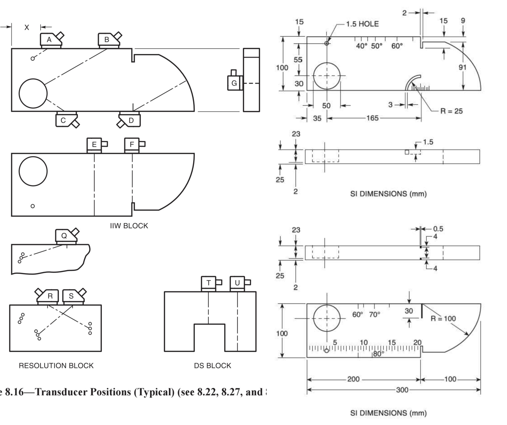
۹۷. هدف اصلی استفاده از بلوک مرجع V1 (IIW) در کالیبراسیون پروب زاویهای چیست؟
الف) اندازهگیری توان تفکیک سطحی
ب) بررسی زاویه شکست واقعی و نقطه خروج بیم
ج) کالیبره کردن حساسیت برای تست Immersion
د) اندازهگیری دمای کوری پروب
۹۸. در تست به روش تماسی با پروب مستقیم، "ناحیه مرده" با کدام یک کاهش مییابد؟
الف) افزایش قطر پروب
ب) استفاده از پروب با دمپر سنگینتر
ج) افزایش ولتاژ پالس
د) کاهش فرکانس پروب
دمپر سنگین، زمان حلقهزنی Ringing کریستال را کوتاه کرده و ناحیه مرده را کم میکند.
۹۹. زاویه بحرانی اول در مبدل موج برشی برای حذف کدام موج ضروری است؟
الف) موج برشی
ب) موج طولی
ج) موج سطحی
د) موج خزشی
۱۰۰. در روش DGS، منحنیها چه رابطهای را نمایش میدهند؟
الف) فرکانس بر حسب قطر پروب
ب) فاصله-دامنه-اندازه عیب
ج) دما بر حسب سرعت صوت
د) زاویه بر حسب جنس ماده
۱۰۱ . کاهش دامنه اکو از ۸۰٪ به ۲۰٪ FSH معادل چند dB است؟
الف) ۶ dB
ب) ۱۲ dB
ج) ۲۰ dB
د) ۴ dB
۱۰۲. کدام عامل بیشترین تأثیر را بر افزایش پراکندگی و تضعیف امواج در فولاد زنگنزن آستنیتی دارد؟
الف) ضخامت قطعه
ب) ساختار دانهدرشت و آنیزوتروپ
ج) فرکانس پایین پروب
د) نوع کوپلانت
۱۰۳. کدام نقص در جوش معمولاً در تست UT به صورت یک اکوی تیز و با دامنه بالا ظاهر میشود که با حرکت جزئی پروب به سرعت محو میشود؟
الف) تخلخل (Porosity)
ب) سرباره خطی (Slag Line)
ج) ترک (Crack)
د) نفوذ ناقص در ریشه (Lack of Penetration)
۱۰۴. در کالیبراسیون Sensitivity با بلوک V1، از کدام ریفلکتور برای تنظیم حساسیت پایه (Reference Level) استفاده میشود؟
الف) انحنای ۲۵ میلیمتری
ب) سوراخ ۱.۵ میلیمتری
ج) شیارهای روی بدنه
د) سطح صاف پشتی بلوک
۱۰۵. در بازرسی جوش شیاری (Butt Weld)، کدام عیب معمولاً درست در نقطه ۱/۲ جهش (Half-Skip) روی صفحه نمایش دیده میشود؟
الف) ترک عرضی در فلز جوش
ب) ذوب ناقص دیواره (Lack of Fusion) در پخ جوش
ج) سرباره در مرکز جوش
د) تخلخل خوشهای
۱۰۶. هنگام استفاده از DAC (Distance-Amplitude Correction) در تست جوش، هدف اصلی از رسم منحنی چیست؟
الف) حذف نویز الکتریکی دستگاه
ب) جبران کاهش دامنه اکو ناشی از افزایش فاصله (Attenuation و واگرایی)
ج) تشخیص نوع عیب از روی شکل منحنی
د) تنظیم زاویه شکست موج در قطعه
۱۰۷. "اسکن چرخشی" (Orbital یا Swivel Scan) عمدتاً برای چه منظوری در تست جوش استفاده میشود؟
الف) اندازهگیری طول دقیق عیب
ب) تعیین زاویه و راستای دقیق عیب (Orientation)
ج) کالیبره کردن حساسیت
د) تشخیص عیوب لایهای در ورق پایه
وقتی یک عیب پیدا میکنید، با چرخاندن پروب حول نقطه تماس (بدون جابجایی مرکز پروب)، میتوانید جهتگیری (Orientation) عیب را تشخیص دهید. حداکثر دامنه اکو وقتی رخ میدهد که بیم کاملاً عمود بر سطح عیب باشد. این تکنیک برای تشخیص ترک از سرباره حیاتی است.
۱۰۸. در تست ورق با پروب مستقیم، کدام الگوی اسکن طبق استاندارد برای اطمینان از پوشش کامل حجم ورق الزامی است؟
الف) فقط یک خط صاف در وسط ورق
ب) اسکن شبکهای (Grid) با همپوشانی ۱۰٪
ج) اسکن زیگزاگی بدون همپوشانی
د) فقط دور لبههای ورق
برای بازرسی کامل ورق از نظر عیوب لایهای (Laminations)، باید کل سطح به صورت شبکهای با خطوط موازی اسکن شود و طبق استاندارد، حداقل ۱۰٪ همپوشانی (Overlap) بین مسیرهای مجاور الزامی است تا هیچ نقطهای از قلم نیفتد.
۱۰۹. هنگام اسکن جوش با پروب زاویهای، حرکت Lateral Scan (حرکت پروب به جلو و عقب عمود بر محور جوش) چه هدفی دارد؟
الف) پیدا کردن عیوب در تمام عمق جوش (Root تا Cap)
ب) اندازهگیری طول عیب
ج) تشخیص ترکهای عرضی
د) کالیبره کردن فاصله
۱۱۰. تفاوت اصلی بین اسکن A-Scan و C-Scan در نمایش نتایج UT چیست؟
الف) A-Scan دامنه بر حسب زمان است و C-Scan نمای مسطح (Plan View) از قطعه.
ب) A-Scan فقط برای پروب زاویهای است و C-Scan برای پروب مستقیم.
ج) A-Scan تصویر رنگی است و C-Scan فقط سیاه و سفید.
د) A-Scan عمق عیب را نشان نمیدهد ولی C-Scan نشان میدهد.
۱۱۱. وجه تمایز اصلی اکوی برگشتی از یک ترک (Crack) و یک سرباره (Slag Inclusion) در حین اسکن چرخشی (Swivel Scan) چیست؟
الف) ترک اکوی ثابت دارد، سرباره متغیر است.
ب) سرباره اکوی تیز و دندانهای دارد، ترک پهن است.
ج) دامنه ترک با چرخش پروب سریعاً افت میکند، ولی سرباره دامنه نسبتاً ثابتی دارد.
د) ترک فقط از یک سمت جوش دیده میشود، سرباره از دو سمت.
ترک سطحی صاف و جهتدار دارد. به محض اینکه زاویه پروب را کمی بچرخانی، موج دیگر عمود بر سطح ترک نیست و اکوی تیز آن ناپدید میشود. اما سرباره که سطحی ناهموار و کروی/حجمی دارد، در زوایای مختلف چرخش همچنان بازتاب نسبتاً پایداری نشان میدهد. به این میگویند "قابلیت چرخش" یا Rotatability عیب.
۱۱۲. در تست جوش شیاری با پروب ۶۰ درجه، یک عیب دقیقاً در محل Root جوش و با عمق منطبق بر ضخامت ورق دارید. محتملترین نوع عیب کدام است؟
الف) ذوب ناقص دیواره (Lack of Sidewall Fusion)
ب) نفوذ ناقص (Incomplete Penetration - IP)
ج) سرباره خطی
د) تخلخل خوشهای
اگر عیب دقیقاً در مرکز ریشه (Root) و در عمقی برابر با ضخامت کامل قطعه دیده شود، به احتمال قریب به یقین Lack of Penetration است. چون نفوذ ناقص یعنی فلز جوش به ریشه نرسیده و آنجا یک فضای خالی عمود بر سطح ایجاد شده که بهترین بازتابنده برای موجی است که از دیواره مقابل برمیگردد.
۱۱۳. حین کالیبره کردن Sensitivity با DAC، اگر عیبی داشته باشیم که دامنه آن ۲۰٪ بالاتر از منحنی مرجع (Reference Curve) باشد، طبق اکثر کدها (مثل AWS D1.1) چه اقدامی باید انجام داد؟
الف) عیب قابل قبول است و نیاز به ثبت ندارد.
ب) عیب باید ثبت (Recordable) شود و نیاز به ارزیابی بیشتر از نظر طول دارد.
ج) قطعه بلافاصله تعمیر یا مردود (Reject) میشود.
د) باید با پروب ۴۵ درجه دوباره تست شود.
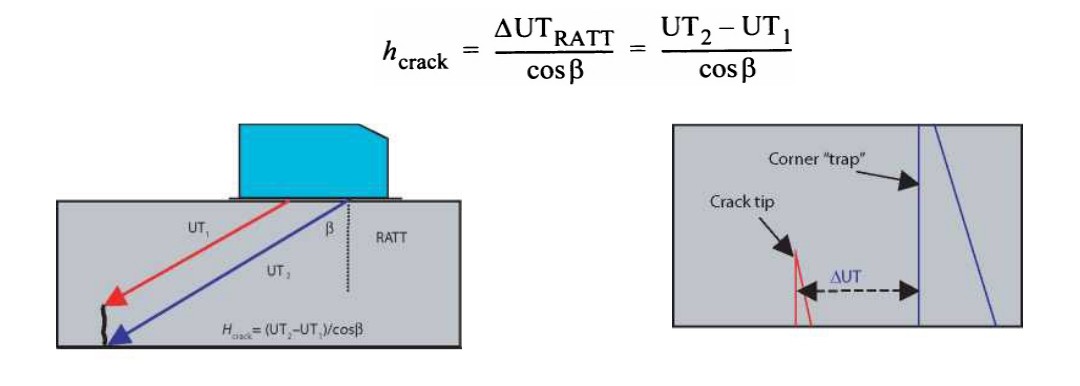
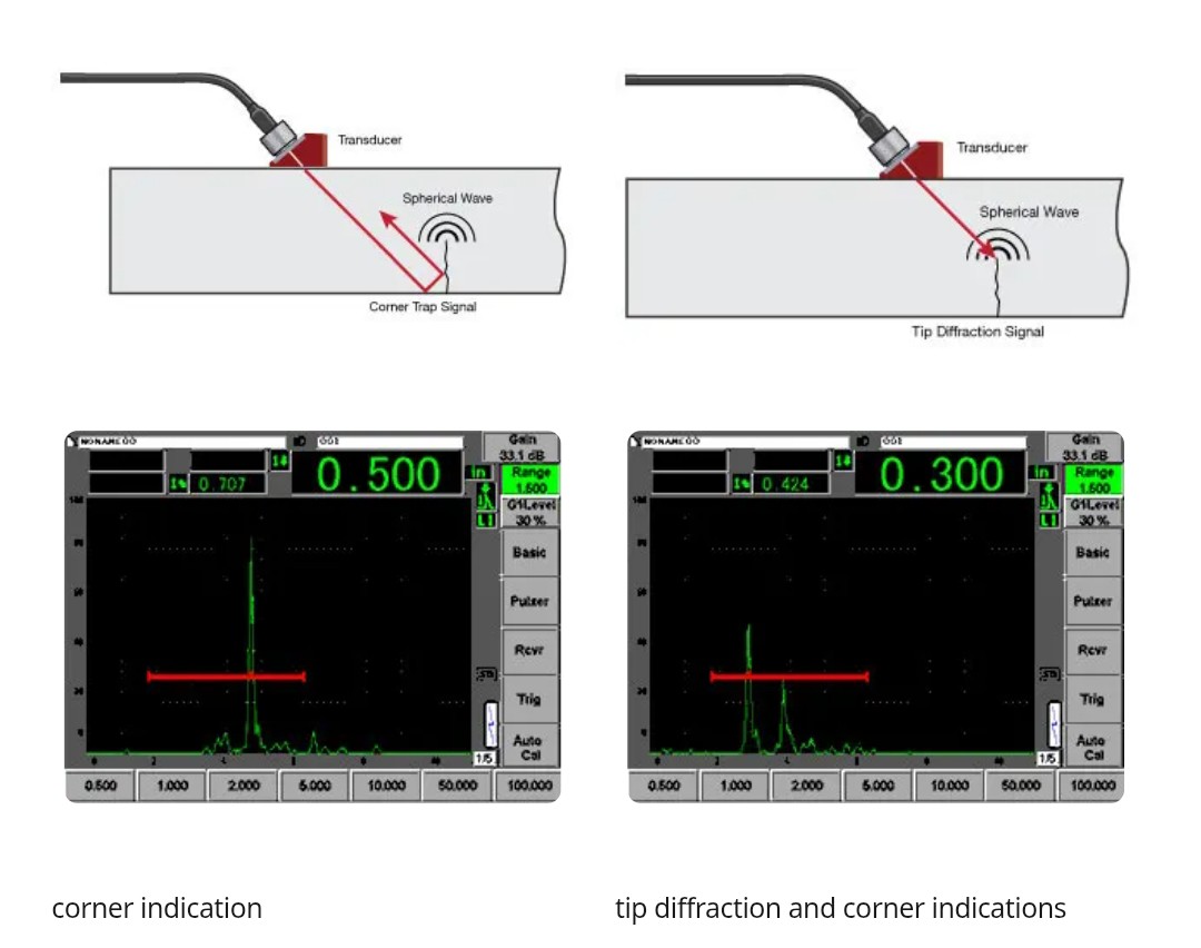
۱۱۴. پدیده "Mode Conversion" در گوشه جوش (Corner Trap) چه تأثیری در تست دارد و چگونه خود را نشان میدهد؟
الف) باعث ناپدید شدن کامل اکوی ریشه میشود.
ب) سیگنال اضافی و گمراهکنندهای در فاصلهای دورتر از ریشه واقعی ایجاد میکند.
ج) دامنه موج برشی را دو برابر میکند.
د) فقط در پروبهای ۴۵ درجه رخ میدهد.
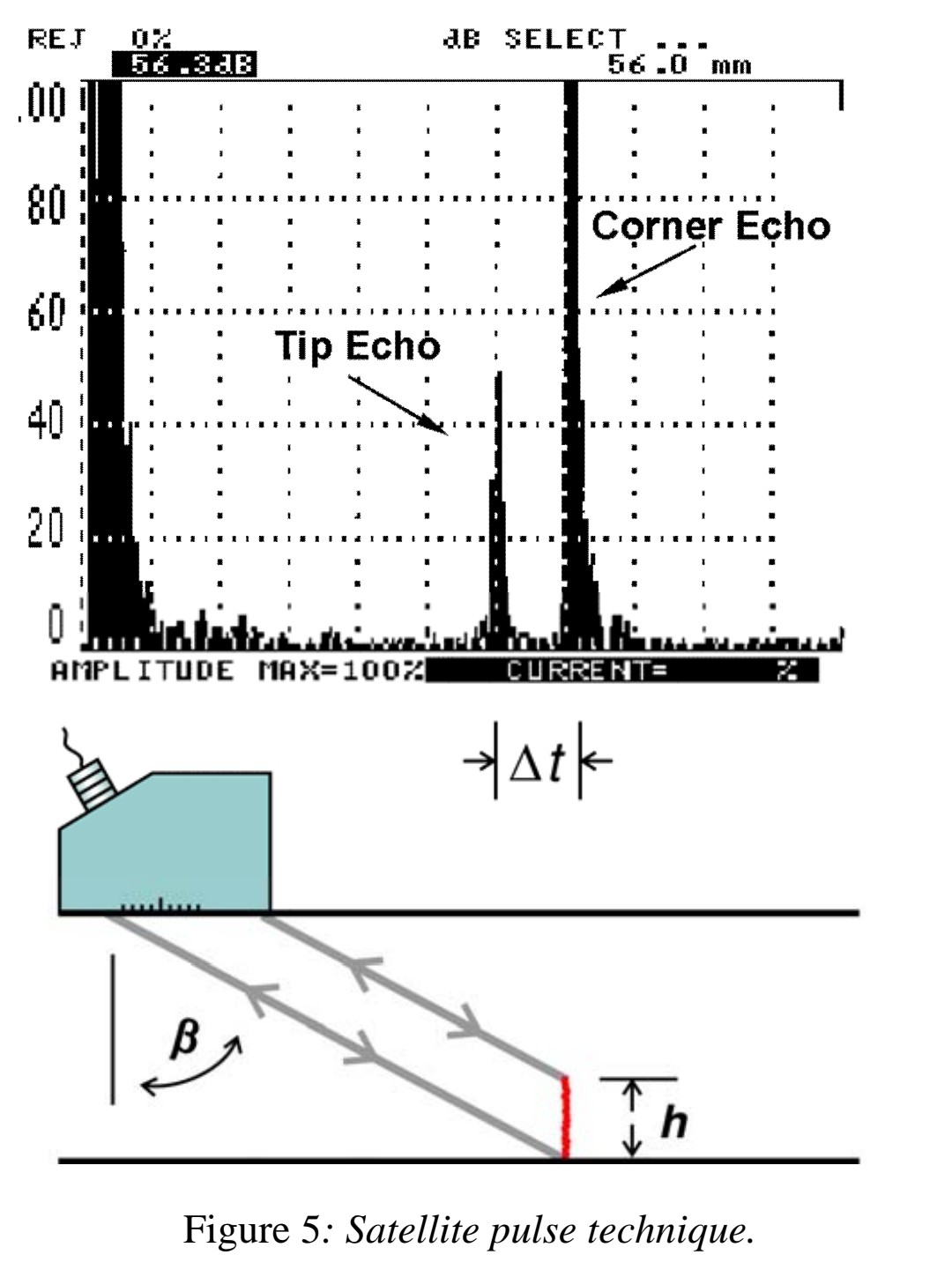
وقتی موج برشی به گوشه جوش میخورد، بخشی از آن تبدیل به موج طولی (Mode Conversion) میشود. این موج طولی با سرعت بیشتر برمیگردد. دستگاه فکر میکند همه چیز با سرعت موج برشی آمده! پس این موج طولی زودتر میرسد و دستگاه آن را به عنوان یک عیب قلابی یا Suprious در عمقی کمتر از ریشه واقعی نشان میدهد.
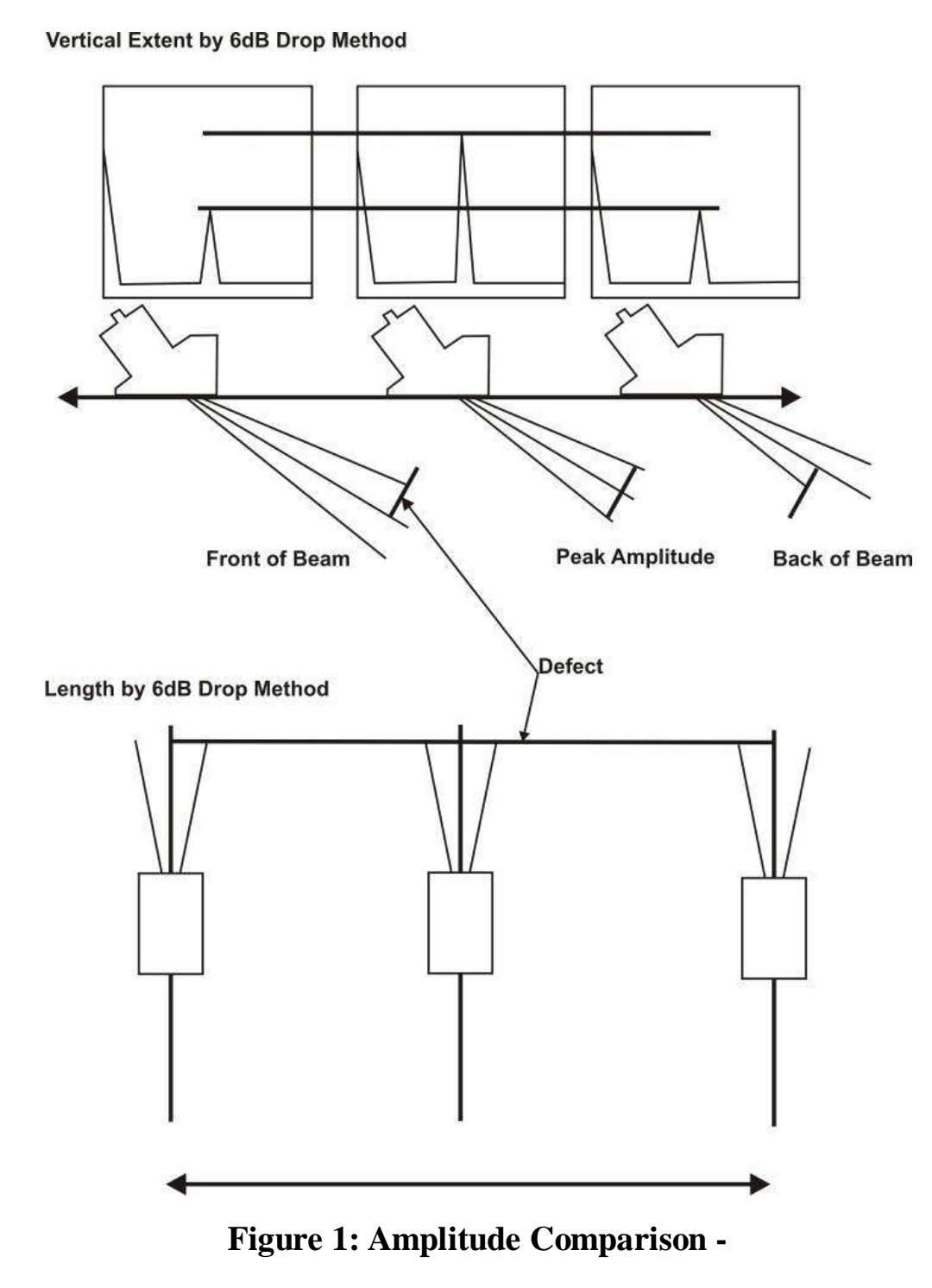
۱۱۵. بهترین روش برای سایزینگ (طولیابی) یک عیب طویل در جوش با پروب دستی کدام تکنیک است؟
الف) تکنیک DGS با پروب مستقیم
ب) تکنیک ۶ دسیبل دراپ (6 dB Drop Method)
ج) مقایسه با اکوی دیوار پشتی
د) اندازهگیری با کولیس روی صفحه نمایش
۱۱۶. تفاوت کلیدی در الگوی اکوی برگشتی از "تخلخل خوشهای" (Cluster Porosity) و "سرباره خطی منفرد" (Single Slag Line) در یک اسکن خطی چیست؟
الف) سرباره یک اکوی تیز و منفرد دارد، تخلخل چندین اکوی کوچک و درهم.
ب) تخلخل یک اکوی واحد با دامنه بالاست، سرباره اکوی پهن دارد.
ج) هر دو دقیقاً شبیه هم هستند و قابل تفکیک نیستند.
د) تخلخل فقط با پروب ۷۰ درجه دیده میشود.
۱۱۷. در بازرسی یک جوش چند پاسه ضخیم، عیبی در فاصله Half-Skip و در عمق منطبق بر محل پخ جوش میبینید که در تست از سمت دیگر جوش (Side B) اصلاً دیده نمیشود. این مشخصه قطعی کدام عیب است؟
الف) نفوذ ناقص در ریشه (IP)
ب) ترک عرضی
ج) ذوب ناقص دیواره (Lack of Sidewall Fusion)
د) تخلخل کرمی (Wormhole)
۱۱۸. در یک جوش ضخیم، دو عیب مختلف در یک موقعیت مشابه روی صفحه نمایش دیده میشوند: یکی ذوب ناقص دیواره (LOF) در پخ جوش و دیگری یک سرباره خطی که دقیقاً پشت آن در فاصله ۳ میلیمتری قرار دارد. اکوی این دو عیب تقریباً روی هم افتاده و تفکیک آنها غیرممکن به نظر میرسد. بهترین اقدام برای افتراق و اثبات وجود دو عیب مجزا چیست؟
الف) افزایش Gain تا حد اشباع و بررسی شکل موج
ب) استفاده از پروب با فرکانس پایینتر (مثلاً ۱ مگاهرتز) برای افزایش نفوذ
ج) استفاده از پروب با فرکانس بالاتر (مثلاً ۵ مگاهرتز) با دمپر سنگین و بررسی عرض پالس
د) تعویض کوپلانت و اسکن مجدد
۱۱۹. در بازرسی جوش شیاری به ضخامت ۲۰ میلیمتر با پروب ۷۰ درجه، دو سیگنال در صفحه نمایش میبینید: یکی در Sound Path معادل ۴۰ میلیمتر (دقیقاً Half-Skip) و دیگری در Sound Path معادل ۵۵ میلیمتر. سیگنال اول تیز و بلند است. سیگنال دوم پهنتر و کوتاهتر است. وقتی پروب را از جوش دور میکنید، سیگنال اول در جهت مخالف (کمتر شدن فاصله) حرکت میکند اما سیگنال دوم در جهت افزایش فاصله حرکت میکند. سیگنال دوم محتملاً چیست؟
الف) نفوذ ناقص (IP) در ریشه
ب) ترک عرضی در جوش
ج) سیگنال کاذب ناشی از تبدیل مد (Mode-Converted Longitudinal Wave) در ریشه
د) اکوی تکراری (Multiple Echo) از دیوار پشتی
وقتی پروب را از جوش دور میکنی، فاصله فیزیکی تا ریشه بیشتر میشود. یک عیب واقعی در ریشه (مثل IP) باید Sound Path بیشتر نشان دهد (حرکت به سمت راست صفحه).
-- اما سیگنال اول (Half-Skip واقعی) درست همین کار را میکند.
-- سیگنال دوم با دور شدن پروب، Sound Path کمتر نشان میدهد (حرکت به سمت چپ صفحه)! این رفتار متناقض، امضای یک موج تبدیلیافته (Mode-Converted) است که مسیر برگشت متفاوتی دارد. خیلی از بازرسها این سیگنال دوم را با IP واقعی اشتباه میگیرند و قطعه را مردود میکنند. این سوال واقعاً سخت و حرفهایه.
۱۲۰. در بازرسی یک جوش شیاری با نفوذ کامل (CJP) به ضخامت ۳۵ میلیمتر، طبق استاندارد باید ریشه (Root) را با پروب ۴۵ درجه اسکن کنید. اما به دلیل محدودیت دسترسی، فقط میتوانید از پروب ۶۰ درجه استفاده کنید. مهمترین مشکلی که با این تعویض برای تشخیص نفوذ ناقص (IP) در مرکز ریشه ایجاد میشود چیست؟
الف) IP اصلاً با پروب ۶۰ درجه دیده نمیشود چون موج از روی آن میپرد.
ب) IP دیده میشود اما دامنه آن کاذباً تقویت شده و باعث مردودی اشتباه میگردد.
ج) موج برشی در ریشه به موج طولی تبدیل میشود و سیگنال کاذب میدهد.
د) IP به جای ریشه، در عمق دیواره فیوژن نمایش داده میشود.
ترک یا نفوذ ناقص در مرکز ریشه، یک بازتابنده عمودی است. برای اینکه موج به این سطح عمودی بخورد و برگردد، باید زاویه تابش نسبتاً بسته باشد (۴۵ درجه ایدهآل است چون بیم پس از برخورد به دیواره مقابل، افقی به ریشه میخورد و برمیگردد). با پروب ۶۰ درجه، بیم به ریشه با زاویه بازتری میخورد. به جای بازگشت به پروب، به سمت بالا و دور از پروب منعکس میشود. نتیجه: IP را نمیبینید و یک عیب بحرانی را از دست میدهید. این دقیقاً همان دلیلی است که استانداردها اصرار دارند اسکن ریشه حتماً با پروب ۴۵ (یا ۵۵) انجام شود.
۱۲۱. در بازرسی جوش شیاری با پروب ۶۰ درجه، سیگنالی درست در موقعیت ریشه (Root) با دامنه بالا میبینید. با حرکت پروب به سمت جوش، سیگنال به تدریج محو میشود. وقتی از سمت مقابل جوش تست میکنید، سیگنال مشابهی در همان موقعیت ظاهر میشود. شکل موج پهن و فاقد تیزی ترک است. این سیگنال محتملاً چیست؟
الف) نفوذ ناقص (IP)
ب) ترک ریشه
ج) بازتاب از تحدب (Root Concavity/Convexity) یا نفوذ اضافی ریشه (Excess Penetration)
د) ذوب ناقص دیواره
-- هندسه خود ریشه جوش (مثل Weld Sink, Excess Penetration, Root Concavity) یک بازتابنده هندسی است، نه عیب. ویژگیهای تمایز آن از IP یا ترک:
-- از دو سمت جوش دیده میشود (برخلاف LOF که یکطرفه است).
-- با حرکت پروب به سمت جوش، Sound Path کاهش یافته و سیگنال محو میشود (چون زاویه تابش به سطح هندسی ریشه دیگر عمود نیست).
-- شکل موج پهن (Broad) است، نه تیز و سوزنی مثل ترک.
هشدار : بسیاری این سیگنال را با IP اشتباه میگیرند و قطعه را مردود میکنند.
۱۲۲. در یک جوش لببهلب با نفوذ کامل، "Cap" داخلی (Root Reinforcement) دارای یک پله (Notch) تیز بین فلز جوش و ورق پایه است. هنگام اسکن با پروب ۴۵ درجه، این پله چه نوع سیگنالی ایجاد میکند و چگونه میتوان آن را از ترک ریشه افتراق داد؟
الف) هیچ سیگنالی ایجاد نمیکند.
ب) سیگنال تیز شبیه ترک؛ تمایز فقط با بررسی چشمی (VT) یا آزمایش PT/MT امکانپذیر است.
ج) سیگنال پهن با دامنه کم؛ افتراق با افزایش Gain.
د) سیگنال تیز اما فقط از یک سمت جوش دیده میشود.
-- یک Notch تیز در محل اتصال ریشه جوش به فلز پایه (Root Notch یا Lack of Blend) دقیقاً مانند یک ترک مصنوعی عمل میکند و اکوی تیز و بلند تولید مینماید. هیچ راه UT محض برای تمایز این ناگسستگی هندسی از یک ترک وجود ندارد. استانداردها (مثل ASME Sec V) صراحتاً میگویند این سیگنالها باید با VT (چشمی) مستقیم یا PT/MT بررسی و رفع ابهام شوند. اگر دسترسی به ریشه نیست، این سیگنال یک "False Call" فنی محسوب میشود که باید در گزارش به آن اشاره کرد.
۱۲۳. چرا اسکن معمولی عمود بر محور جوش (اسکن D یا Lateral Scan) با پروب ۷۰ درجه، بسیاری از ترکهای عرضی (Transverse Cracks) را تشخیص نمیدهد و چه اسکنی برای این ترکها الزامی است؟
الف) چون ترک عرضی موازی بیم است؛ باید از اسکن موازی (Longitudinal) یا مورب ۴۵ درجه روی کلاهک جوش استفاده کرد.
ب) چون ترک عرضی فقط در ریشه است؛ باید با پروب مستقیم تست کرد.
ج) چون ترک عرضی عمود بر سطح است؛ باید Tandem Scan انجام داد.
د) چون ترک عرضی فقط با پروب ۰ درجه دیده میشود.
-- ترک عرضی عمود بر محور جوش قرار دارد. وقتی شما پروب را عمود بر جوش (Lateral) میکشید، بیم شما موازی ترک عرضی است و هیچ بازتابی دریافت نمیکند (یا فقط یک بازتاب ضعیف از نوک آن). برای تشخیص ترک عرضی، بیم باید موازی محور جوش یا با زاویه کم (مثلاً ۴۵ درجه مورب) بتابد. این اسکن (Scan C طبق AWS D1.1) روی کلاهک جوش (Cap) یا از روی ورق مجاور جوش انجام میشود و در بسیاری از کدها اجباری است.
۱۲۴. در اسکن مورب برای ترکهای عرضی روی کلاهک جوش سنبادهنخورده (As-Welded Cap)، کدام مشکل عمده باعث سیگنالهای کاذب و خطای ارزیابی میشود و راه حل استاندارد آن چیست؟
الف) تضعیف زیاد به دلیل دانههای درشت جوش — راه حل: کاهش فرکانس به ۱MHz.
ب) بازتاب از شیارهای بین پاسهای جوش (Ripple/Toe) روی سطح کلاهک — راه حل: سنباده زدن کلاهک همسطح با فلز پایه.
ج) نویز الکتریکی — راه حل: تعویض کابل.
د) تبدیل مد در کلاهک — راه حل: استفاده از پروب ۴۵ درجه.
-- سطح ناهموار کلاهک جوش (Weld Ripples و Toe) پر از شیارهای ریز و تیز است که برای امواج صوتی مانند یک آینه محدب عمل کرده و سیگنالهای کاذب فراوان (Grass) ایجاد میکند. استانداردها (ASME Sec V و AWS D1.1) صراحتاً میگویند: برای اسکن ترک عرضی، کلاهک جوش باید به صورت همسطح (Flush Ground) سنباده زده شود تا این سیگنالهای کاذب حذف شوند. بدون این کار، اسکن غیرقابل اعتماد و پر از False Call است. نکته: منظور از سنباده زدن، حذف کامل کلاهک نیست، بلکه صاف کردن سطح تا زبری مجاز است.
۱۲۵. در بازرسی جوش شیاری به ضخامت ۲۵ میلیمتر با پروب ۶۰ درجه، اکویی در عمق دقیق ۲۵ میلیمتر (Root) با دامنه ۹۰٪ FSH مشاهده میکنید. با حرکت پروب به اندازه ۵ میلیمتر به سمت جوش، Sound Path از ۵۰ میلیمتر به ۴۶ میلیمتر کاهش یافته و دامنه به ۴۰٪ افت میکند. سپس با حرکت پروب به موازات محور جوش (Longitudinal)، این اکو در سرتاسر طول جوش و با الگوی کاملاً یکنواخت تکرار میشود. محتملترین تفسیر چیست و چرا؟
الف) نفوذ ناقص (IP) ممتد در کل طول جوش — قطعه باید مردود شود.
ب) تقعر ریشه (Root Concavity) ناشی از جمعشدگی فلز جوش — یک بازتابنده هندسی قابل قبول.
ج) ترک ریشه ممتد — نیاز به سایزینگ دقیق با 6dB Drop دارد.
د) ذوب ناقص دیواره — فقط یک سمت جوش را بررسی کردهاید.
-- تغییر Sound Path با حرکت Lateral: وقتی به جوش نزدیک میشوید، Sound Path کم میشود. برای یک IP واقعی (که در مرکز ریشه است)، Sound Path با نزدیک شدن به جوش باید افزایش یابد نه کاهش. کاهش یعنی بازتابدهنده در سطح زیرین و نزدیکتر از ریشه واقعی است.
-- یکنواختی ممتد در طول جوش: IP واقعی به ندرت در کل طول جوش کاملاً یکنواخت است. اما Root Concavity ناشی از انقباض جوش، یک فرورفتگی پیوسته و هندسی است که الگوی بازتاب کاملاً یکنواخت و تکرارشونده ایجاد میکند.
-- دامنه متغیر با حرکت: IP با تغییر زاویه تابش، سریعاً محو میشود. Concavity رفتار نرمتری دارد.
۱۲۶. در تست یک جوش با پروب ۴۵ درجه، اکوی ریشه را در Half-Skip مشاهده میکنید. تصمیم میگیرید تست "Half-Skip to Full-Skip" انجام دهید. وقتی پروب را آنقدر از جوش دور میکنید که بیم پس از برخورد به ریشه، به دیواره مقابل بخورد و برگردد (Full-Skip)، چه مشاهدهای Excess Penetration را از IP افتراق میدهد؟
الف) IP در Full-Skip محو میشود ولی Excess Penetration همچنان دیده میشود.
ب) Excess Penetration در Full-Skip دو برابر بزرگتر از Half-Skip دیده میشود.
ج) هر دو عیب در Full-Skip ناپدید میشوند.
د) IP در Full-Skip اکوی قویتری میدهد.
-- نفوذ ناقص (IP): یک سطح عمودی صاف در مرکز ریشه است. در Half-Skip، بیم ۴۵ درجه پس از برخورد به دیواره مقابل، افقی به IP میخورد و عالی برمیگردد. در Full-Skip، بیم اول به ریشه میخورد، سپس به دیواره، و دیگر زاویه عمود بر IP را از دست میدهد. IP در Full-Skip به شدت ضعیف یا نامرئی میشود.
-- Excess Penetration (نفوذ اضافی ریشه): یک برآمدگی محدب است که از هر زاویهای بخشی از موج را پراکنده میکند و سطحی ناهموار دارد. در Half-Skip و Full-Skip، هر دو یک بازتاب (هرچند ضعیفتر و پهنتر) ایجاد میکند. پس اگر اکو در Full-Skip هم ماند، هندسه است نه IP.
۱۲۷. در حین بازرسی یک جوش لببهلب (Butt Weld) با دسترسی فقط از یک سمت، اکوی تیزی در ریشه میبینید که شبیه ترک است. دسترسی به ریشه برای VT وجود ندارد. کدام روش دستی و فوری UT میتواند در همان لحظه به شما بگوید این سیگنال از یک "Root Suck-back" (برگشتگی ریشه) است یا یک ترک واقعی؟
الف) افزایش Gain تا حد اشباع
ب) تست با پروب ۷۰ درجه اضافی
ج) لمس ریشه جوش از سمت مقابل با انگشت آغشته به کوپلانت و مشاهده افت و نوسان اکو
د) کاهش فرکانس پروب
-- یک فرورفتگی در ریشه است (ناشی از انقباض بیش از حد) که سطح ریشه را به داخل میکشد. این عیب هندسی، سطح نسبتاً صافی دارد و موج را به خوبی برمیگرداند.
ترفند انگشت (Finger Damping Test):
-' از همکار بخواهید نوک انگشت آغشته به گریس یا کوپلنت را روی ریشه (از سمت داخل لوله یا مخزن) بگذارد.
-- اگر سیگنال مربوط به Root Suck-back باشد: انگشت مانند دمپر عمل کرده و اکو به شدت افت کرده، نوسان میکند یا کاملاً محو میشود.
-- اگر ترک باشد: ترک یک ناپیوستگی در عمق فلز است و لمس سطح خارجی ریشه تأثیری بر بازتاب داخلی ترک ندارد. اکو ثابت میماند.
--این تکنیک ساده اما بسیار حرفهای، جزو دانش تجربی بازرسهای Level II است
ویژگی هندسه ریشه (Geometry) عیب واقعی (IP/Crack)
-- یکنواختی در طول جوش کاملاً یکنواخت و پیوسته متغیر، منقطع
-- رفتار در Full-Skip همچنان دیده میشود IP محو میشود
-- تست Finger Damping اکو افت میکند یا ناپدید میشود اکو ثابت است
-- تغییر Sound Path با نزدیک شدن کاهش مییابد افزایش مییابد
-- شکل موج پهن (Broad) تیز (Sharp/Peaky)
یک کریستال با قطر ۱۲ میلیمتر و فرکانس ۲ مگاهرتز در فولاد (سرعت ۵۹۰۰ متر بر ثانیه) چند میلیمتر میدان نزدیک دارد؟
۱۲.۲ میلی متر
در یک کریستال ۱۰ میلیمتری با فرکانس ۴ مگاهرتز در آب (سرعت ۱۴۸۰ متر بر ثانیه)، زاویه واگرایی (نیمزاویه) را حساب کنید. حدود ۲.۶ درجه
(فرمول: sinθ = ۱.۲۲ × (λ ÷ D))
یک کریستال کوارتز به ضخامت ۱ میلیمتر و سرعت ۵۷۰۰ متر بر ثانیه، چه فرکانس رزونانسی دارد؟