کلینیک فوق تخصصی دانش آموخته لوله کشی صنعتی ۸۳-۸۴ ( نفت و گاز ) - مایترکاری
سایتی نو و نخست برای ارائه راهنمای ساخت انواع شابلون پایپینگ به Fabricator ها و بالا بردن دانش ریاضی ایشانکلینیک فوق تخصصی دانش آموخته لوله کشی صنعتی ۸۳-۸۴ ( نفت و گاز ) - مایترکاری
سایتی نو و نخست برای ارائه راهنمای ساخت انواع شابلون پایپینگ به Fabricator ها و بالا بردن دانش ریاضی ایشاندرباره من
 This topic is a little part of programming in access , We have reached to this goal just with efforts and more exercises also studying the Microsoft Office Documents and their various forums
ادامه...
This topic is a little part of programming in access , We have reached to this goal just with efforts and more exercises also studying the Microsoft Office Documents and their various forums
ادامه...
نظرسنجی
آیا این مطالب برای شما مفید واقع شد
روزانهها
همه- حد پذیرش تست مایعات نافذ Asme Viii Appendix 8
- افسانه شیان فان
- انهدام شبکه جاسوسی در یمن شکست غرب و اروپا در یمن
- طرح نعل اسبی سایت موشکی در سوریه آماده برای شلیک به اسرائیل
- قضیه تالس
- داروی اوسلتامیویر (تامی فلو) برای درمان و پیشگیری از آنفولانزا داروی آنفولانزا
- عزیز جون پرستو ... کنسرت کاروانسرا
- Y Ducting Connector تبدیل Y شکل گالوانیزه Air Ducting
- سایت
- تفسیر قانون پذیرش پزشکی بدون کنکور المپیک 2024
- طرح جدید پذیرش بدون کنکور پزشکی المپیکیها مدال بیار بدون کنکور رشته پزشکی بخون
- مسابقات جهانی آرایش
- جولان افاغنه در ایران از خرید تا اجاره ملک
- یا حسین میر حسین
- کیست تخمدان مراجعه به پزشک زنان قبل از وقوع یا مرحله کم خطر بودن
پیوندها
- برخورداستوانه و مخروط
- برنچ
- رفتارشما
- Jalali Calendar میلادی-شمسی
- Whats app دانلود
- Fabrication راهنمای ساخت
- Slope In Piping روش محاسبه شیب در پایپینگ
- شکستگی و پروتز گردن ران ( فمور )
- ساپورت دامی - زانوئی چند تکه - شلوارک
- مهسا امینی دستگیری بعلت بدحجابی ، از سکته او در پلیس امنیت در جریان بحث و وفات در بیمارستان کسری تهران دهه سوم شهریور ۱۴۰۱
- رحم اجاره ای اخاذی بین ۱۰۰ تا ۲۰۰ میلیون و ماهی ۳ میلیون در سال ۱۴۰۱ و نبود قانون
- مهسا امینی - اعتراضات اواخرشهریور ۱۴۰۱
- اعتراضات شهریور۱۴۰۱
- احکام 18+
- قانون Control Banding بازرسی محوطه کاری ، سرزمینی یا مرزهای دریایی
- The day of revenge is near
- Maximum Allowable Stress Section ii part D تنش مجاز متریال A106 Grade B در دمای ۴۳۵ درجه سانتیگراد
- Thickness Calculation of blind flange مثال هایی برای محاسبه ضخامت ورق برای ساخت فلنج کور بر اساس UG-34
- Bolt root and tensile stress area
- Pressure-Temperature rating B16.5
- Yield Strength for material A105 section ii part D استحکام تسلیم فلنج A105 جدول Y-1 سکشن ii در دماهای مختلف
- Required Wall thickness حداقل ضخامت مورد نیاز براساس بند ug-34 و فرمول یک اپندیکس 2 ( سرهای مسطح دایره ای )
- ( Required Wall Thickness ( Mininmum مثال از حداقل ضخامت Blind flange سایز ۳۴ اینچ
- Flange rating Maximum Design Pressure - حداکثر فشار طراحی بر اساس Asme B16.5
- دختران ایرانی زیر پای سگ های ارتش آمریکا توضیحاتی درباره وضعیت برخی دختران در زمان شاه
- Maximum Stress value SA-312 TP316L حداکثر تنش مجاز متریال در دماهای مختلف
- Asme PCC-1 appendix H-O bolt stress - bolt root area
- Root area + Tensile stress area Bolt
- Bolt root + tensile area ASME B1-1 for threads
- داستان سید مهدی قوام و زن ...
- شارلی ابدو فرانسه
- تجاوز وحشیانه چند افغان به یک زن جوان در فرحزاد
- ورزش با حرکات موزون + موسیقی
- دامی ساپورت انواع مختلف نصب
- اپلیکیشن دامی ، مایتر زانویی و شلوارک
- YJC.IR
- عیوب جوش
ابر برچسب
شابلون برنچ Dummy support دامی ساپورت Miter Unequal Branch Branch Miter bend piping Ut Pipe Branch Dummy پایپینگ PWHT مهسا امینی ردیوسر Pipe To Cone ELBOW DEGREE مخروط ناقص تنش زدایی impact testجدیدترین یادداشتها
همه- سوالات UT ASNT LEVEL II × Sign In Sign Up FAQ created by Eugene Cawley on 12/17/2018. Resource summary Question 1 Question Generally, the best...
- فرکانس 2 مگاهرتز در التراسونیک - مشکل فرکانس ۲ مگاهرتز (طول موج بلند) تخلخل یک عیب کروی و مدور است. طبق قوانین فیزیک صوت: عبور موج: فرکانس ۲ مگاهرتز...
- کالیبراسیون دستگاه UT با بلوک V1 و پراب زاویه ای
- کالیبراسیون دستگاه UT برای آزمایش قطعه بر اساس AWS D1.1 تمام کالیبراسیون و آزمایش قطعات باید با قرار دادن Reject Control در وضعیت Off انجام گردد. کالیبراسیون حساسیت و مسافت می...
- Trusonic ultrasonic dB increment Alarm You can adjust the display range if your measurement in range. The coarse adjustment from 25, 50,...
- Trusonic ultrasonic
- محاسبه ارتفاع ترک توسط زمان پرواز یا time of flight ارزیابی ارتفاع ترک بر اساس اندازهگیری نسبی مسیر فراصوت بین سیگنالهای نوک ترک و تله گوشه ترک تکنیک کاهش 6 دسیبل Gain
- Lack of side wall fusion echo in ut اکوی بلند ، تک ، باریک در محور افقی دستگاه یا time base و اکوی ضعیف در اسکن از سمت دیگر. در اسکن چرخشی یا دورانی اکو به...
- Sizing Defect 6DB Drop تکنیک نیم دامنه / افت ۶ دسیبل: تکنیک نیم دامنه برای تعیین انتهای یک ناپیوستگی زمانی استفاده میشود که طول آن از اندازه...
- کالیبره دستگاه UT برای تست قطعه 50 میلیمتری
- Leg1 And Leg2 in UT
- Straight Probe
- کالیبره حساسیت در استاندارد AWS D1.1 و سایزینگ N6.2.2 Sensitivity Calibration (Standard). The search unit should be placed over the standard reflectors at a minimum...
- Crack dimension in ut Range : در تست با پروب های زاویه ای آگاهی از زاویه دقیق پروب، نقطه ایندکس پروب و طول مسیر صوت تا یک نقطه منعکس کننده...
- تابع AWS دستگاه UTS کالیبره مسافت انجام شده ... کلیدهای میانبر روی صفحه برای دسترسی به صفحات یا کم و زیاد کردن دسیبل یا حرکت دادن gate و...
- الکترود مصرفی ، پیش گرم و محدوده تنش زدایی در AWS D10.8
- جوشکاری فلزات مختلف طبق API RECOMMENDED PRACTICE 582 6.3 Dissimilar Metal Welding When joining dissimilar ferritic steels (P-No. 1 though P-No. 5), filler metal shall...
- جوشکاری فلزات مختلف طبق API RECOMMENDED PRACTICE 582 -Dissimilar Metal Welding When joining dissimilar ferritic steels (P-No. 1 though P-No. 5), filler metal shall conform...
- تعیین ناپیوستگی ها کالیبراسیون مسافت یا محور افقی : -Rejection خاموش باشد. -اول Probe Delay را صفر می کنیم. -Angle را برای پراب زاویه ای...
- عیب یابی با پراب نرمال قطعه ای با ضخامت 100 میلیمتر جهت عیب Lamination مورد آزمون قرار میگیرد Range را روی 100 قرار می دهیم تا اولین Backwall...
- Slag inclusion in ut عیب حجمی
- کالیبره حساسیت با بلوک V2 طبق استاندارد 7963
- تعیین ایندکس پراب در UT Finding Index point Probe index به دستگاه داده میشود تا Skip distance یا فاصله جلوی پراب تا عیب را نمایش بدهد و در...
- کالیبراسیون با بلوک V1 و V2 برای کالیبره ، P-Delay را حتما صفر قرار می دهیم و Reject Control هم باید off باشد بلوک IIW دارای انحنای 100 میلیمتر...
- Cluster Porosity in UT
- مراحل کالیبراسیون دستگاه UT چرا "cal+enter" مهم است: دقت: کالیبراسیون مناسب برای به دست آوردن قرائت دقیق ضخامت و تشخیص عیوب درون یک قطعه...
- CRACK در تست UT و Sizing به شکل سیگنال توجه کنید اسکن چرخشی را انجام دهید SIDE WALL FUSION CRACK ( ROTATIONAL ) TOE CRACK ROOT CRACK ( LEG 1 )...
- Pulse Echo Examination نوع عیب : - LOP یا عدم نفوذ ( در دسته غیر حجمی یا NON VOLUMETERIC ) : در جوش Single V پیک بالایی از هر دو طرف ورق جوش...
- تابع AWS در دستگاه CTS1002 PLUS کلید CAL سرعت ماده و تأخیر پروب و همچنین زاویه را کالیبره میکند. مراحل کار با AWS : پراب زاویه ای : - حرکت پراب روی...
- محاسبه طول برش در پایپینگ در مثال زیر X CUT و Y CUT را بدست آورید
بایگانی
- بهمن 1404 1
- دی 1404 1
- آذر 1404 4
- آبان 1404 6
- مهر 1404 1
- شهریور 1404 14
- مرداد 1404 12
- تیر 1404 4
- خرداد 1404 7
- اردیبهشت 1404 4
- فروردین 1404 1
- بهمن 1403 8
- دی 1403 5
- آذر 1403 3
- آبان 1403 8
- مهر 1403 15
- شهریور 1403 28
- مرداد 1403 3
- تیر 1403 2
- خرداد 1403 12
- اردیبهشت 1403 20
- فروردین 1403 2
- اسفند 1402 3
- بهمن 1402 11
- دی 1402 24
- آذر 1402 55
- آبان 1402 17
- مهر 1402 1
- شهریور 1402 3
- مرداد 1402 1
- خرداد 1402 3
- اردیبهشت 1402 3
- فروردین 1402 4
- اسفند 1401 10
- بهمن 1401 15
- آذر 1401 8
- آبان 1401 25
- مهر 1401 7
- شهریور 1401 13
- مرداد 1401 6
- تیر 1401 2
- خرداد 1401 13
- اردیبهشت 1401 1
- دی 1400 2
- آذر 1400 15
- آبان 1400 44
- شهریور 1400 6
- مرداد 1400 27
- تیر 1400 38
- خرداد 1400 16
- اردیبهشت 1400 4
- فروردین 1400 10
- اسفند 1399 8
- بهمن 1399 6
- دی 1399 3
- آذر 1399 2
- شهریور 1399 9
- فروردین 1399 10
- بهمن 1398 12
- آذر 1398 8
- آبان 1398 5
جستجو
آمار : 316608 بازدید
Powered by Blogsky
کالیبره حساسیت در استاندارد AWS D1.1 و سایزینگ
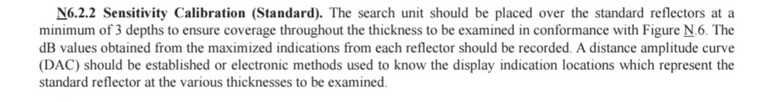
N6.2.2 Sensitivity Calibration (Standard). The search unit should be placed over the standard reflectors at a minimum of 3 depths to ensure coverage throughout the thickness to be examined in conformance with Figure N.6. The dB values obtained from the maximized indications from each reflector should be recorded. A distance amplitude curve (DAC) should be established or electronic methods used to know the display indication locations which represent the standard reflector at the various thicknesses to be examined.
N9. Weld Discontinuity Sizing and Location Methods
N9.1 Calibration. Calibration should be based upon depth from the smface in confonnance with N6. Discontinuities may be sized with the highest achievable level of accuracy using the methods described in this section; however, the user is reminded that UT, like all other NDT methods, provides relative discontinuity dimensions. Discontinuity orientation and shape, coupled with the limitations of the NDT method, may result in significant variations between relative and actual dimensions.
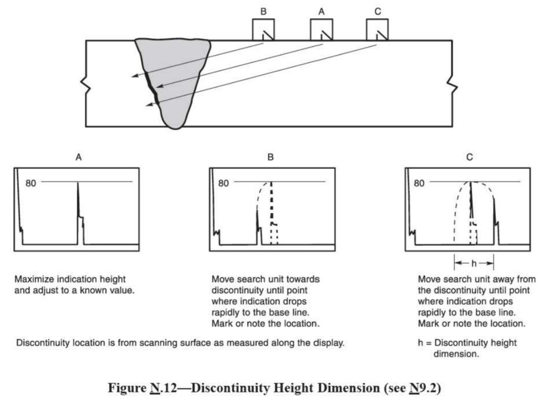
ارتفاع : ارتفاع ناپیوستگی ( اندازه عمق ) می بایست با استفاده از روشهای ذیل انجام پذیرد :
- ارتفاع نشانه می بایست با حرکت دادن پراب به سمت یا از ناپیوستگی مطابق با A از شکل 12 به حداکثر برسد.ارتفاع نشانه می بایست به یک مقدار مشخص تنظیم شود ( مثلا 80 درصد از ارتفاع صفحه یا 80%FSH )
- پراب می بایست بطرف ناپیوستگی حرکت داده شود تا ارتفاع نشانه به سرعت و پیوسته به سمت خط پایه شروع به کم شدن نماید. محل لبه جلویی ( چپ ) نشانه در محل B در شکل 12 نسبت به مقیاس خط پایه افقی نمایشگر باید یادداشت شود.
- برای تعیین بعد ارتفاع ناپیوستگی باید اختلاف ریاضی بین B و C بدست آید.
N9.2 Height. The discontinuity height (depth dimension) should be determined using the following methods:
N9.2.1 The indication height should be maximized by moving the search unit to and from the discontinuity in confonnance with A of Figure N.12. The indication height should be adjusted to a known value (e.g., 80% of full screen height [FSH]).
N9.2.2 The search unit should be moved towards the discontinuity until the indication height begins to drop rapidly and continuously towards the base line. The location of the leading (left) edge of the indication at location B in Figure N.12 in relation to the display horizontal base line scale should be noted. A 0.10 in [2.5 mm] division scale or metric scale should be used.
N9.2.3 The search unit should be moved away from the discontinuity until the indication height begins to drop rapidly and continuously towards the base line. The location of the leading edge of the indication at location C in Figure 0.12 in relation to the display horizontal base-line scale should be noted.
N9.2.4 The mathematical difference between B and C should be obtained to determine the height dimension of the discontinuity.
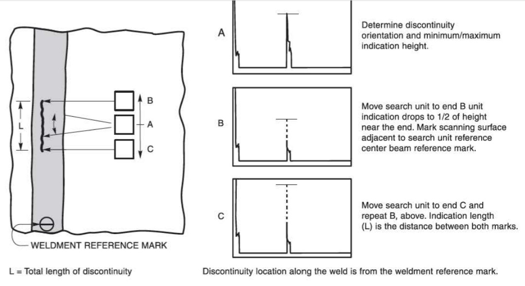
طول :
طول.طول ناپیوستگی می بایست با استفاده از روشهای های زیر مشخص گردد:
- جهت گیری ناپیوستگی می بایست با دستکاری پراب برای تعیین صفحه و مسیر قوی ترین نشانه مطابق با شکل 13 مشخص شود.
- پراب می بایست در حالیکه بخشی از نشانه همیشه روی صفحه نمایش قابل مشاهده باشد به یک انتهای ناپیوستگی منتقل شود تا زمانیکه نشانه بطور کامل به خط پایه برسد. سپس پراب باید به سمت ناپیوستگی به عقب حرکت داده شود تا ارتفاع به 50 درصد حداکثر ارتفاع اولیه که در نزدیکی انتها مطابق با B شکل 13 به دست آمده بود، برسد.محل انتهای ناپیوستگی روی سطح اسکن یا روی خط جوش می بایست علامت زده شود . علامت گذاری باید به دقت با خط ریز انجام شود .
- تمام موارد بالا برای سمت مخالف طبق C شکل 13 باید بدانید انجام شده و مارک گردد.
- طول ناپیوستگی می بایست از اندازه گیری بین دو محل علامت زده شده طبق شکل 13 بدست آید.
N9.3 Length. The discontinuity length should be determined using the following methods:
N9,3.1 The orientation of the discontinuity should be determined by manipulation of the search unit to determine the plane and direction of the strongest indication in conformance with A of Figure N.13.
N9.3.2 The search unit should be moved to one end of the discontinuity while keeping part of the indication visible on the display at all times until the indication drops completely to the base line. The search unit should be moved back towards the discontinuity until the indication height reaches 50% of the maximum height originally obtained near the end in conformance with B of Figure N.13. The location should be marked on the end of the discontinuity on the scanning surface or welded in line with the search unit maximum indication mark. This marking should be performed carefully using a fine-line marking method.
N9.3.3 The steps above should be repeated for locating the opposite end of the discontinuity in conformance with C of Figure N.13 and should be marked carefully.
N9.3.4 The length of the discontinuity should be obtained by measuring the distance between the two marks in conformance with Figure N.13