کلینیک فوق تخصصی دانش آموخته لوله کشی صنعتی ۸۳-۸۴ ( نفت و گاز ) - مایترکاری
سایتی نو و نخست برای ارائه راهنمای ساخت انواع شابلون پایپینگ به Fabricator ها و بالا بردن دانش ریاضی ایشانکلینیک فوق تخصصی دانش آموخته لوله کشی صنعتی ۸۳-۸۴ ( نفت و گاز ) - مایترکاری
سایتی نو و نخست برای ارائه راهنمای ساخت انواع شابلون پایپینگ به Fabricator ها و بالا بردن دانش ریاضی ایشاندرباره من
 This topic is a little part of programming in access , We have reached to this goal just with efforts and more exercises also studying the Microsoft Office Documents and their various forums
ادامه...
This topic is a little part of programming in access , We have reached to this goal just with efforts and more exercises also studying the Microsoft Office Documents and their various forums
ادامه...
آمار : 308327 بازدید
Powered by Blogsky
فرکانس 2 مگاهرتز در التراسونیک
- مشکل فرکانس ۲ مگاهرتز (طول موج بلند)
تخلخل یک عیب کروی و مدور است. طبق قوانین فیزیک صوت:
عبور موج: فرکانس ۲ مگاهرتز دارای طول موج بلندی (حدود ۱.۶ میلیمتر در فولاد) است. اگر قطر حفرههای تخلخل کوچکتر از طول موج باشد، امواج به سادگی از روی آنها عبور کرده و هیچ بازتابی (اکویی) به دستگاه برنمیگردانند
طول موج = سرعت صوت در قطعه / فرکانس پراب
3240000/2000000
حساسیت پایین:
این فرکانس برای عیوب تخت و بزرگ (مثل ترک) طراحی شده و در برابر تخلخلهای ریز عملاً «نابینا» است
چرا AWS بر فرکانس ۲ مگاهرتز تاکید دارد؟
استاندارد AWS D1.1 به این دلیل فرکانس ۲ تا ۲.۲۵ مگاهرتز را الزامی کرده است که: فرمول محاسباتی (Indication Rating): محاسبات تعیین شدت عیب در AWS (فرمول \(D=A-B-C\)) بر اساس ویژگیهای پرتو در این فرکانس طراحی شده است تا اثرات پخش بیش از حد پرتو یا تضعیف نامتعارف در فولادهای ساختمانی کنترل شود.
نفوذ در فولادهای کربنی: این فرکانس توازن بهینهای بین قدرت نفوذ (برای عبور از دانههای درشت فولاد ساختمانی) و حساسیت (برای تشخیص عیوب بحرانی) ایجاد میکند.
انتخاب زاویه بر اساس ضخامت (Table 6.7 یا ۸.۷) :
در استاندارد AWS D1.1، برای ضخامت ۳۰ میلیمتر (که در بازه بیش از ۲۰ تا ۳۸ میلیمتر قرار میگیرد)، استفاده از پراب ۷۰ درجه مجاز و طبق جدول انتخابی، برای اسکن بخشهای بالایی، میانی و پایینی جوش توصیه شده است.
در استاندارد AWS D1.1، برای ضخامت ۳۰ میلیمتر (که در بازه بیش از ۲۰ تا ۳۸ میلیمتر قرار میگیرد)، استفاده از پراب ۷۰ درجه مجاز و طبق جدول انتخابی، برای اسکن بخشهای بالایی، میانی و پایینی جوش توصیه شده است.
AWS D1.1 2025
UT
8.24.4 Straight-Beam Testing of Base Metal.
Calibration for straight-beam testing of base metal shall be made with the search unit applied to Face A of the base metal and performed as follows:
8.24.4.1 Sweep.
The horizontal sweep shall be adjusted for distance calibration to present the equivalent of at least two plate thicknesses on the display.
8.24.4.2 Sensitivity.
The sensitivity shall be adjusted at a location free of indications so that the first back reflection from the far side of the plate will be 50% to 75% of full screen height.
8.24.5 Calibration for Angle-Beam Testing.
Calibration for angle-beam testing shall be performed as follows (see Annex G, G2.4 for alternative method).
The horizontal sweep shall be adjusted to represent the actual sound-path distance by using the IIW type block or alternative blocks as described in 8.22.1. The distance calibration shall be made using either the 5 in [125 mm] scale or 10 in [250 mm] scale on the display, whichever is appropriate. If, however, the joint configuration or thickness prevents full examination of the weld at either of these settings, the distance calibration shall be made using 15 in or 20 in [400 mm or 500 mm] scale as required. The search unit position is described in 8.27.2.3.
NOTE: The horizontal location of all screen indications is based on the location at which the left side of the trace deflection breaks the horizontal base line.
بر اساس استاندارد AWS D1.1 از سوراخ 1.5 میلیمتری بلوک V1 اکوی ماکزیمم گرفته می شود و سپس ارتفاع آن با دستکاری Gain به 40 تا 60 درصد صفحه رسانده میشود و دسیبل خوانده شده بعنوان دسیبل مرجع با حرف b یادداشت میشود بعلت تضعیف صوت در قطعه طبق جدول ، 14 یا 20 دسیبل قبل از تست جوش به دسیبل مرجع اضافه میشود شروع به اسکن میکنید در صورت دریافت سیگنال اکو اگر سیگنال از صفحه بیرون زده بود می توانید ارتفاع آنرا کم کنید ( منظور کم کردن gain دستگاه ) و سپس با حرکت مرسوم حداکثر ارتفاع را بگیرید ( البته چک کنید در نوار جوش افتاده شود با اندازه Ra یا فلش جلو در دستگاه ) ارتفاع آنرا به 40 تا 60 درصد صفحه برسانید دسیبل قرائت شده را بعنوان حرف a یا نشانه عیب یادداشت کنید به یاد داشته باشید عدد Sa یا Sound path را نیز یادداشت کنید چون برای بدست آوردن فاکتور تضعیف یا c مهم است. بعد از تعیین نرخ عیب یا حرف d به سراغ اندازه گیری طول عیب بروید در حالیکه در ارتفاع 60 قرار دارد به چپ و راست جاروب کنید تا ارتفاع به نصف تقلیل یابد ( کاهش 6 دسیبل ) و از وسط پراب در محل جوش علامت بزنید ..برای اسکن مابقی طول جوش دسیبل دستگاه را به همان عدد b باضافه 14 یا 20 دسیبل قرار دهید ... طبق جدول در استاندارد AWS برای مسیر صوت تا 65 میلیمتر 14 دسیبل به دسیبل دستگاه اضافه میشود.
The zero reference level sensitivity used for discontinuity evaluation (“b” on the ultrasonic test report, Annex O, Form O–11) shall be attained by adjusting the calibrated gain control (attenuator) of the discontinuity detector, meeting the requirements of 8.21, so that a maximized horizontal trace deflection (adjusted to horizontal reference line height with calibrated gain control [ attenuator]) results on the display between 40% and 60% screen height, in confonnance with 8.27.2.4
8.27 .2.4 Amplitude or Sensitivity Calibration Procedure.
The transducer shall be set in position A on the IIW type block (any angle). The maximized signal shall then be adjusted from the 0.060 in [1.59 mm] hole to attain a horizontal reference-line height indication (see Annex G, G2.4 for alternative method). The maximum decibel reading obtained shall be used as the "Reference Level, b" reading on the Test Repo1t sheet (Annex 0, Fom1 0-11) in confonnance with 8.22.1.
8.25.6.3 Maximum Indication.
When a discontinuity indication appears on the screen, the maximum attainable indication from the discontinuity shall be adjusted to produce a horizontal reference level trace deflection on the display. This adjustment shall be made with the calibrated gain control (attenuator), and the instrument reading in decibels shall be used as the “Indication Level, a,” for calculating the “Indication Rating, d,” as shown on the test report (Annex O, Form O–11).
8.25.6.4 Attenuation Factor.
The “Attenuation Factor, (c),” on the test report shall be attained by subtracting 1 in [25 mm] from the sound-path distance and multiplying the remainder by 2 for U.S. Customary Units or by 0.08 for SI Units.
The factor (c) shall be rounded to the closest significant decimal place (0.1). Values less than 0.05 shall be reduced to the lower 0.1 and those of 0.05 or greater increased to the higher 0.1.
The factor (c) shall be rounded to the closest significant decimal place (0.1). Values less than 0.05 shall be reduced to the lower 0.1 and those of 0.05 or greater increased to the higher 0.1.
8.25.6.5 Indication Rating.
The “Indication Rating, (d),” in the UT Report, Annex O, Form O–11, represents the algebraic difference in decibels between the indication level and the reference level with correction for attenuation as indicated in the following expressions:
Instruments with gain in dB: a – b – c = d
Instruments with attenuation in dB: b – a – c = d
The indication rating shall be rounded to the nearest whole number (1 dB) value. Resulting decimal values less than 0.5 dB shall be rounded down and those of 0.5 dB or greater shall be rounded up.
8.25.7 Length of Discontinuities.
The length of discontinuities shall be determined in conformance with the procedure described in 8.29.2.
هر ناپیوستگی غیرقابل قبولی می بایست همراه با طول و عمق روی قطعه نوشته شود.
8.25.9 Identification of Rejected Area.
Each unacceptable discontinuity shall be indicated on the weld by a mark directly over the discontinuity for its entire length. The depth from the surface and indication rating shall be noted on nearby base metal.
سرجوش های مردود در تست التراسونیک می بایست با روش های مجاز در بند 7.25 تعمیر شوند و مجدد تست التراسونیک شوند.
8.25.10 Repair.
Welds found unacceptable by UT shall be repaired by methods allowed by 7.25 of this code. Repaired areas shall be retested ultrasonically with results tabulated on the original form (if available) or additional report forms.
8.29.2 Angle-Beam (Shear) Testing.
The following procedure shall be used to determine lengths of indications which have dB ratings more serious than for a Class D indication. The length of such indication shall be determined by measuring the distance between the transducer centerline locations where the indication rating amplitude drops 50% (6 dB) below the rating for the applicable discontinuity classification. This length shall be recorded under “discontinuity length” on the test report. Where warranted by discontinuity amplitude, this procedure shall be repeated to determine the length of Class A, B, and C discontinuities.
8.27.2 Shear Wave Mode (Transverse)
8.27 .2.1 Index Point.
The transducer sound entiy point (index point) shall be located or checked by the following procedure:
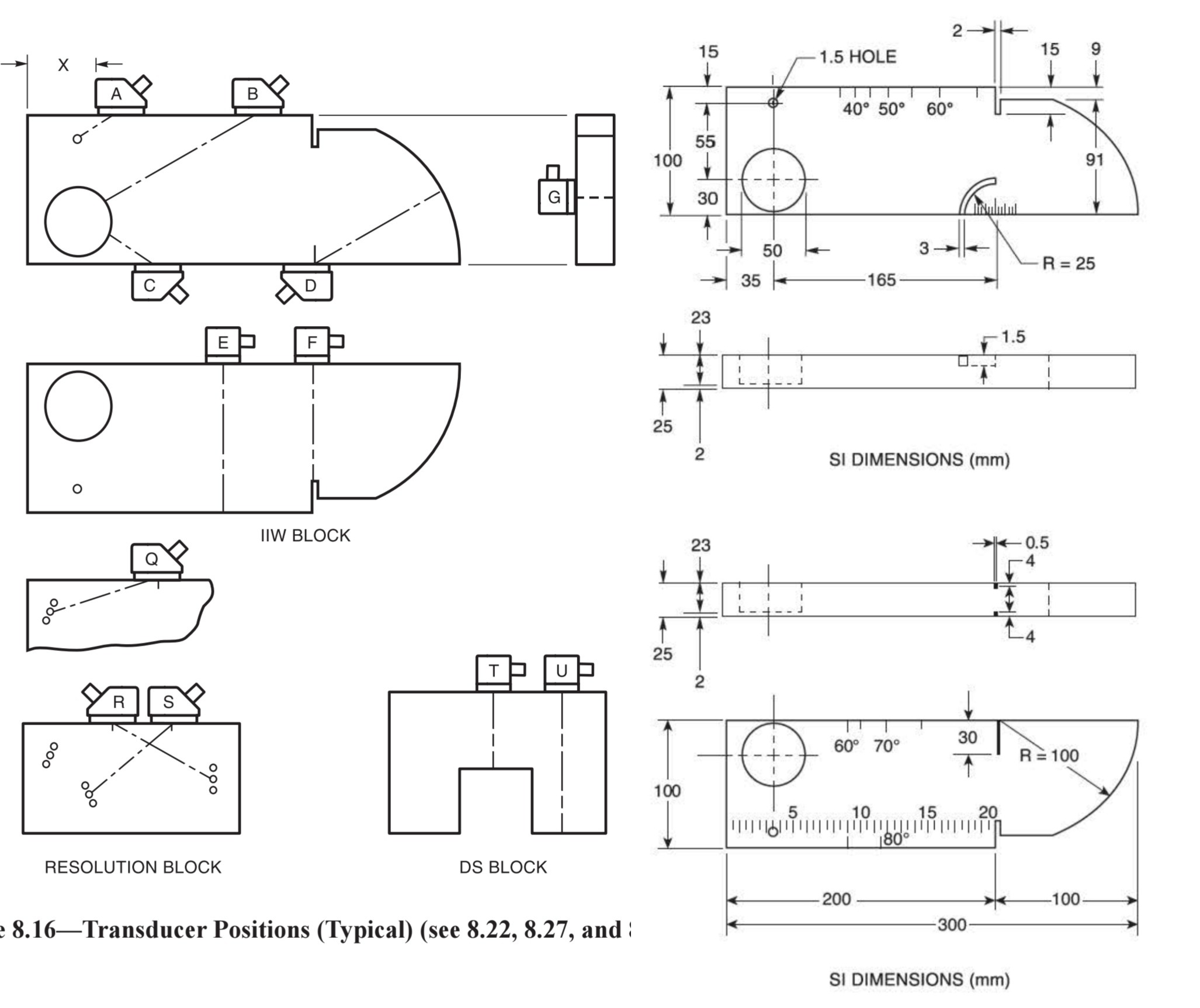
(1) The transducer shall be set in position Don the IIW type block
(2) The transducer shall be moved until the signal from the radius is maximized. The point on the transducer which aligns with the radius line on the calibration block is the point of sound entiy (see Annex G, G2. l for alternative method).
8.27 .2.2 Angle.
The transducer sound-path angle shall be checked or determined by one of the following procedures:
(1) The transducer shall be set in position B on IIW type block for angles 40° through 60°, or in position C on IIW type block for angles 60° through 70° (see Figure 8.16).
(2) For the selected angle, the ti·ansducer shall be moved back and forth over the line indicative of the transducer angle until the signal from the radius is maximized. The sound entiy point on the transducer shall be compared with the angle mark on the calibration block (tolerance± 2°) (see Annex G, G2.2 for alternative methods).
8.27.2.3 Distance Calibration Procedure.
The transducer shall be set in position D on an IIW type block (any angle). The instmment shall then be adjusted to attain one indication at 4 in [100 mm on a metric block] and a second indication at 8 in [200 mm on a meti-ic block] or 9 in [225 mm on a metric block] (see Annex G, G2.3 for alternative methods).
8.27 .2.4 Amplitude or Sensitivity Calibration Procedure.
The transducer shall be set in position A on the IIW type block (any angle). The maximized signal shall then be adjusted from the 0.060 in [1.59 mm] hole to attain a horizontal reference-line height indication (see Annex G, G2.4 for alternative method). The maxinmm decibel reading obtained shall be used as the "Reference Level, b" reading on the Test Repo1t sheet (Annex 0, Fom1 0-11) in confonnance with 8.22.1.