به گزارش ایسنا به نقل از روابط عمومی ارتش، ۵۶ تن از کارکنان جان برکف ارتش جمهوری اسلامی ایران در راه دفاع از کشور و امنیت مردم قدر شناس ایران اسلامی در تقابل با رژیم صهیونسیتی، به فیض شهادت رسیدند.
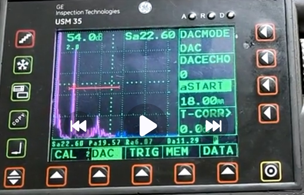
با بلوک V1 یا V2 دستگاه UT را کالیبره کنید ( کالیبره مسافت یا Sweep range ) شاخص و زاویه دقیق پراب را تعیین کنید برای کالیبره محور عمودی طبق استاندارد نمی توانید از سوراخ 1.6 میل بلوک V1 استفاده کنید باید برای سایز 20 و کمتر از بلوک ناچ دار که مشابه بلوک تست است استفاده کنید و منحنی DAC بکشید ( برای جبران مسافت در عمق های مختلف ، چون عیب ها در عمق های مختلف و بسته به سایز آن دامنه کمتری دارند . شما اینکار را انجام می دهید تا عیوب خطرناک که در عمق هستند را از دست ندهید ) اولین منحنی DAC مرجع است و بعدی DAC 50 درصد و DAC 20 درصد را رسم می کنید ،( در دستگاه های دیجیتال معمولا دو منحنی دیگر را ترسیم می نماید ) .
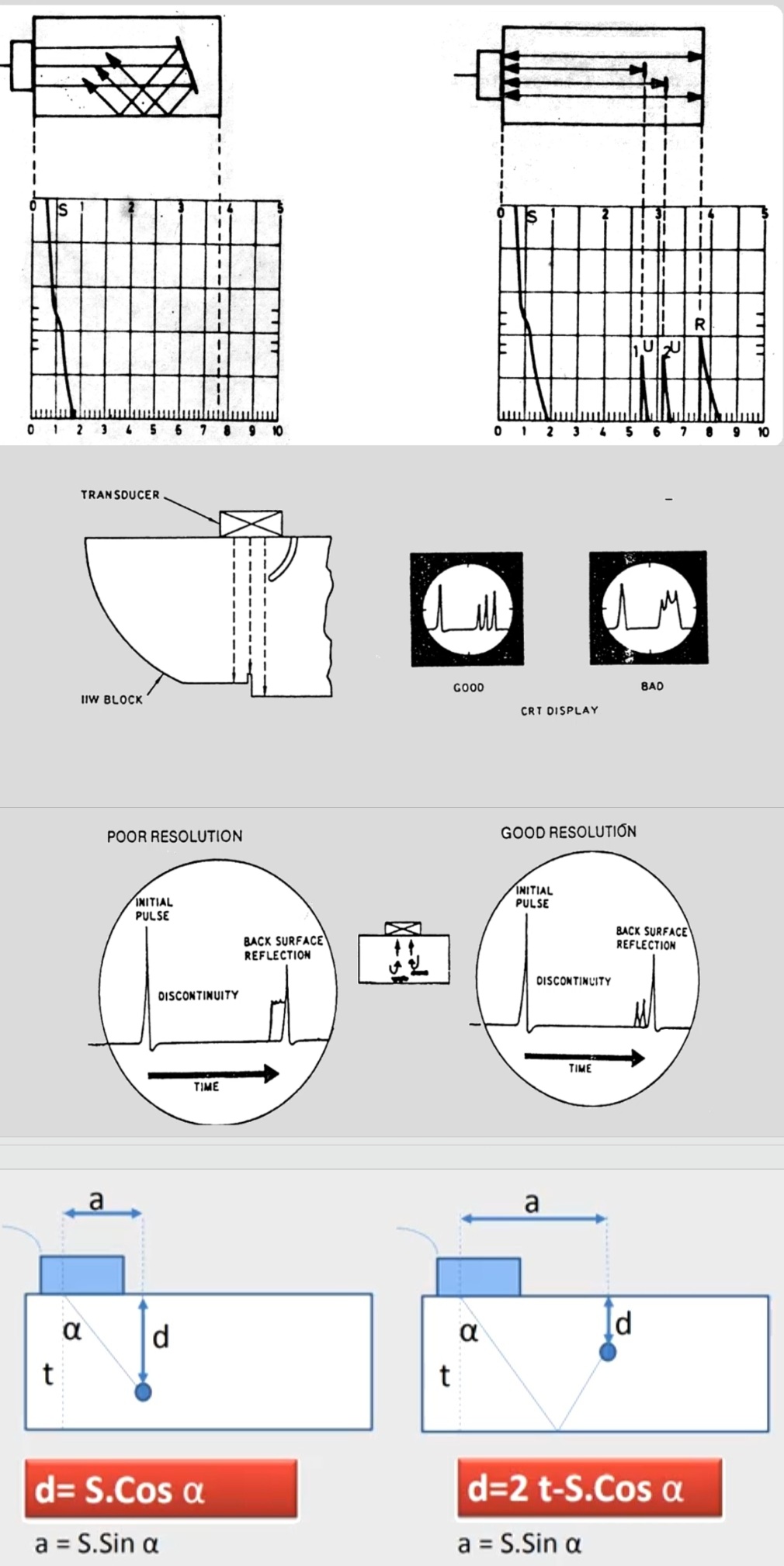
برای تست Resolution یا وضوح بازتابنده های نزدیک بهم ( ویژگی دستگاه و پراب : ترکیبی است ) حتما از بلوک RC استفاده کنید باید توانایی تشخیص و تفکیک 3 قله از بازتابنده ها را داشته باشد.
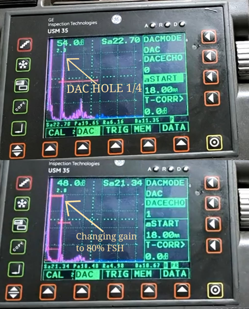
ترسیم DAC :
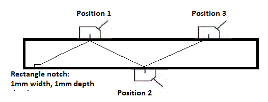
سیگنال از ناچ داخلی گرفته میشود حداکثر ارتفاع آنرا در صفحه بدست آورده و با gain آنرا به 80 درصد FSH برسانید. حال پراب را روی ناچ بیرونی ببرید و بدون تغییر gain در Leg2 از ناچ بیرونی سیگنال بگیرید ( حتما ماکزیمم سیگنال را پیدا کنید در هر سه نقطه .. در ASME حتما باید برای رسم DAC سه نقطه ترسیم شود ) . دوباره پراب را در روی لوله و سمت ناچ داخلی می بریم و حداکثر ارتفاع سیگنال Leg3 ناچ داخلی را می گیریم .. حتما از 2t× tana یا 3t×tana برای یافتن محل دقیق پراب استفاده کنید تا سیگنال ها را اشتباه نگیرید.
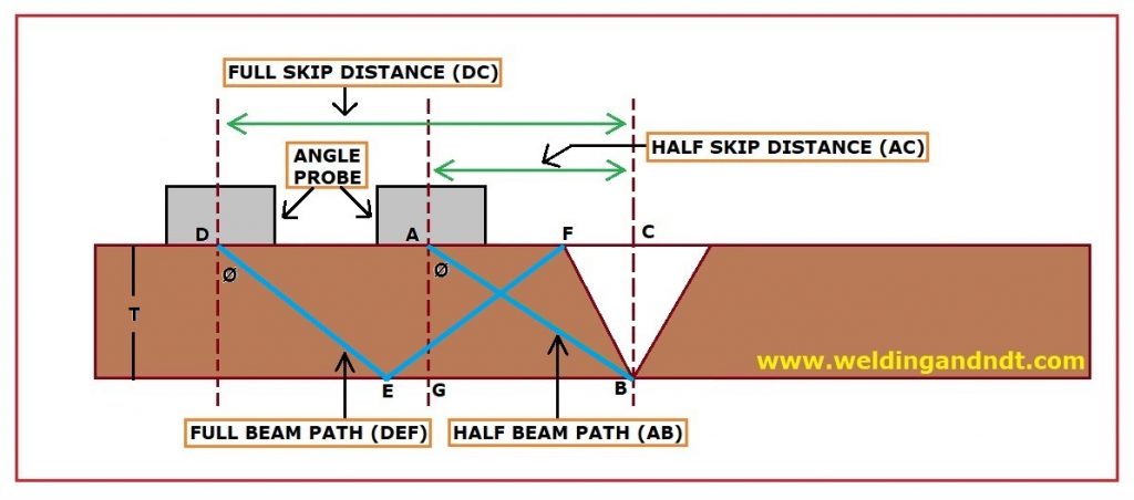
SURFACE DISTANCE = 2T/COSA × SINA = 2TTANA
قبل از اسکن کردن با پراب زاویه ای می بایست با پراب نرمال از پنجه جوش تا Full skip یا Leg2 را برای بررسی Lamination اسکن کنیم


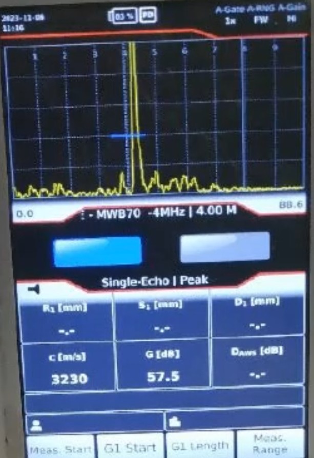
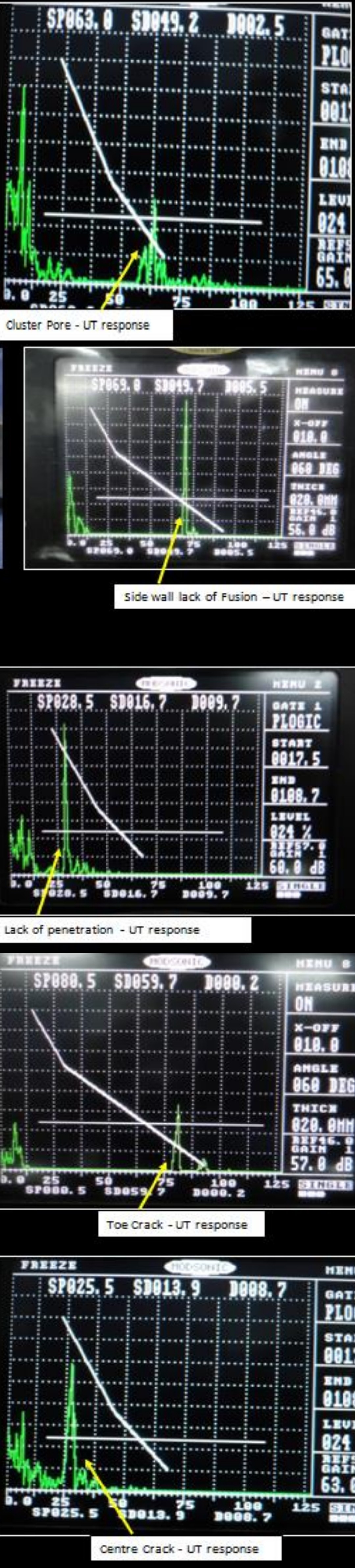
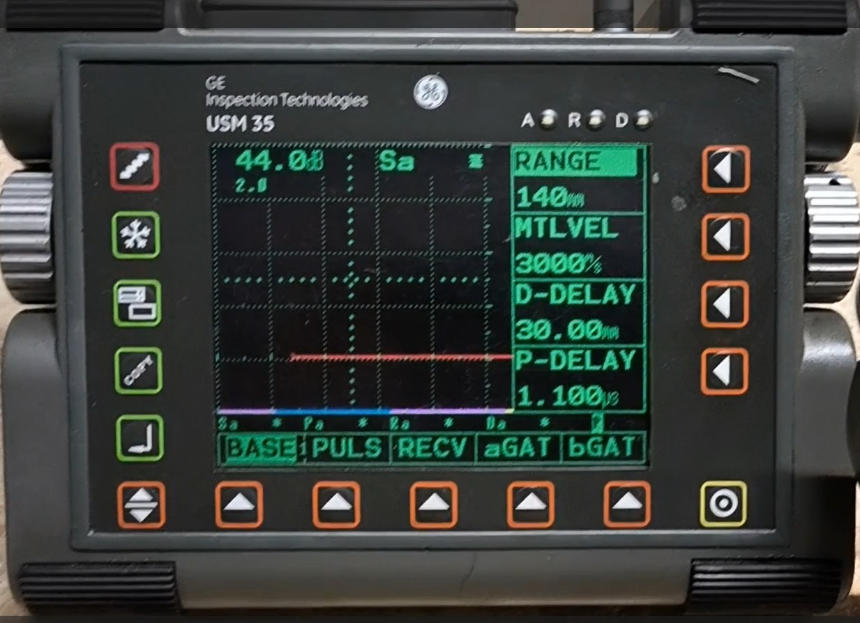
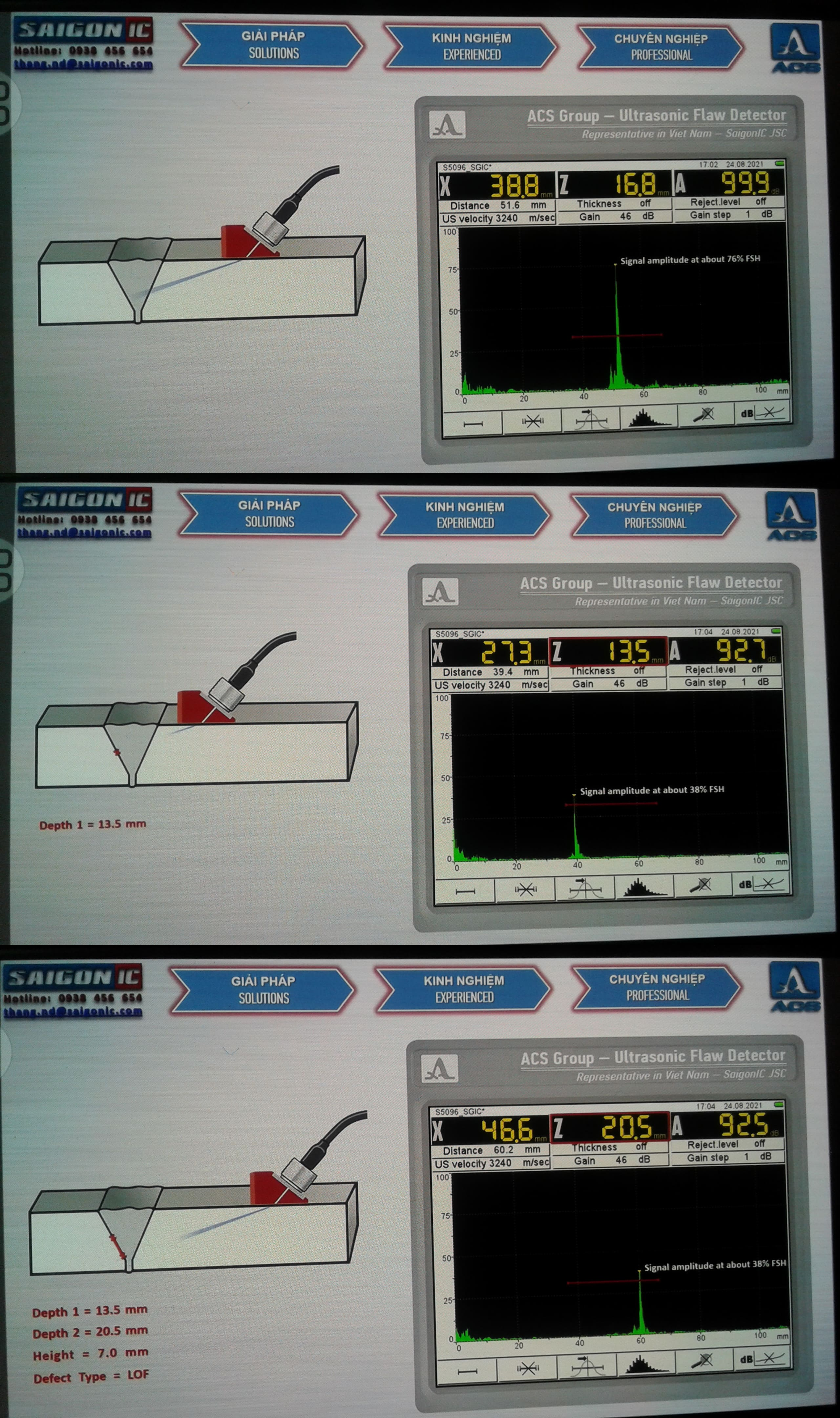
در شکل بالا عدد gain ( تقویت کننده سیگنال توسط آمپلی فایر ) را ببینید عدد 62 را نشان میدهد این همان gain مرجع + 6 dB است یعنی اسکن را با 56+6 دسیبل بالاتر از gain مرجع شروع کرده.
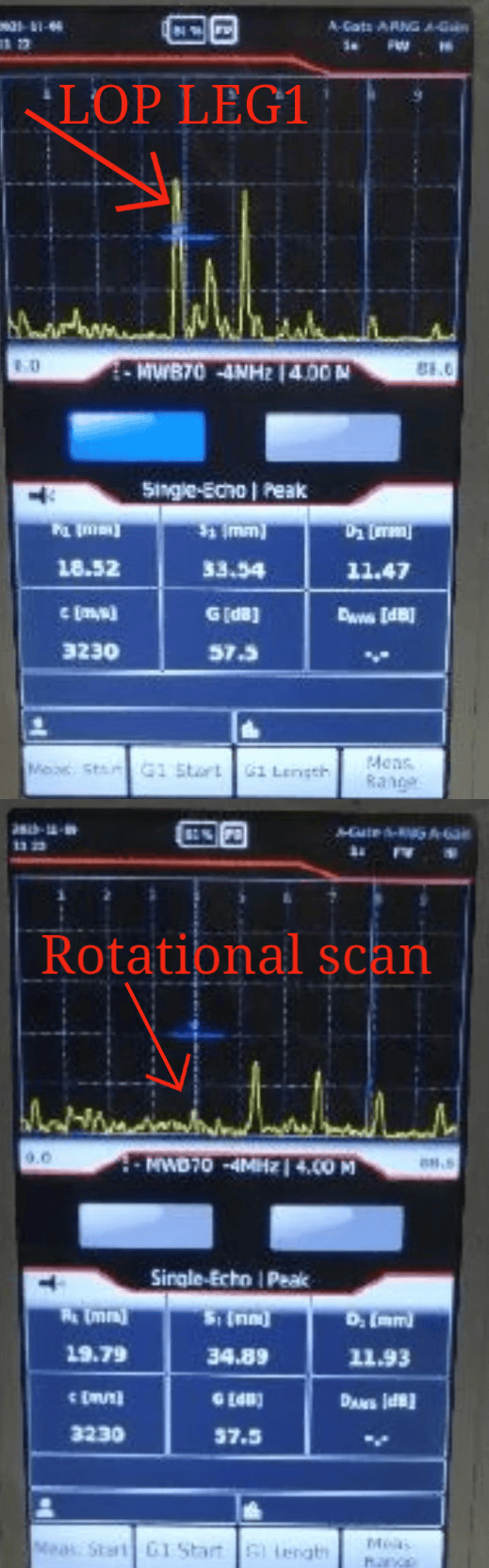
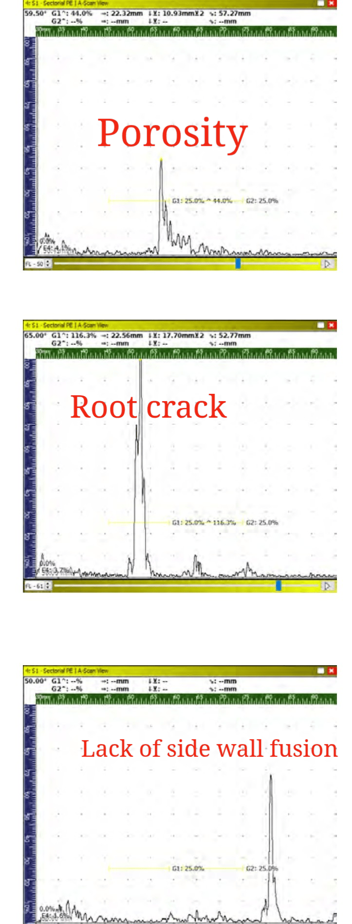
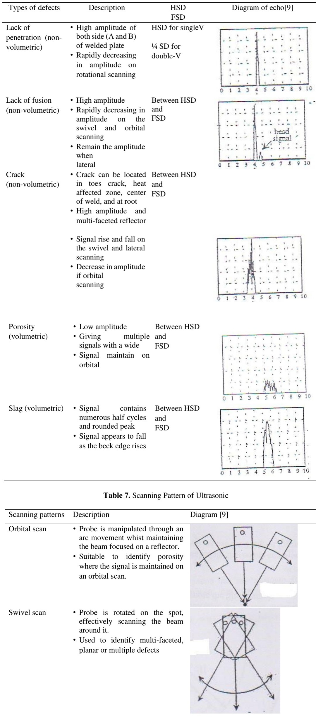
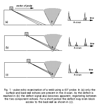
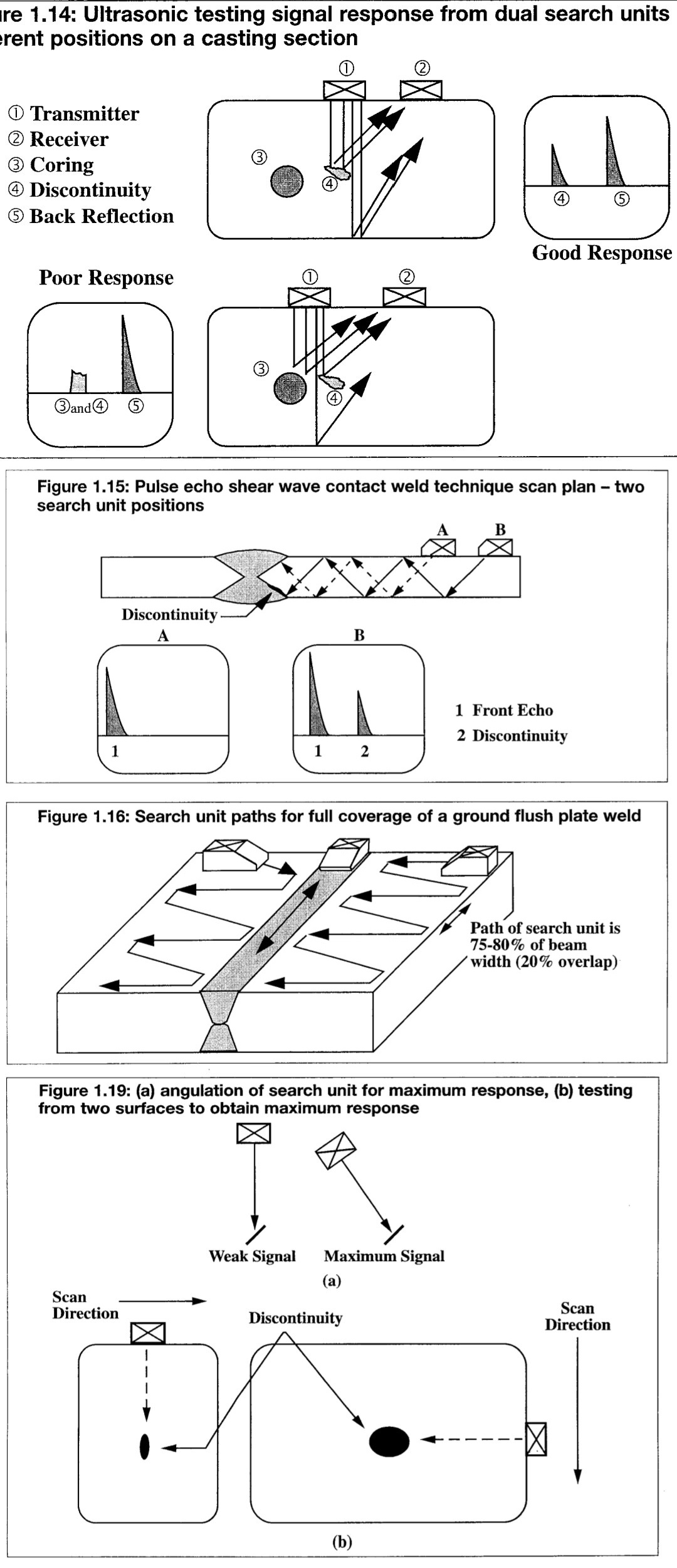
سیگنالی مشاهده شده اولی چون این عیب خطی است و جهتدار دار مثل آیینه عمل کرده و سریعا صوت به پراب برمیگردد سیگنال کنار آن از مهره های جوش است که انرژی کمتری را به پراب رسانده ( دلیل پرتو های بیشتری از مهره ها عبور کرده و در طول ضخامت ادامه یافته ولی سیگنال اول بعلت آمپدانس صوتی بالا تقریبا 99 درصد از صوت Reflected شده است ) برای صد در صد تشخیص دادن عیب حتما باید از دو طرف اسکن شود از یک طرف دامنه زیاد و از یک طرف چون عمود به دسته پرتو نیست دامنه خیلی کمی دارد.
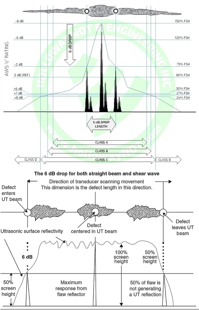
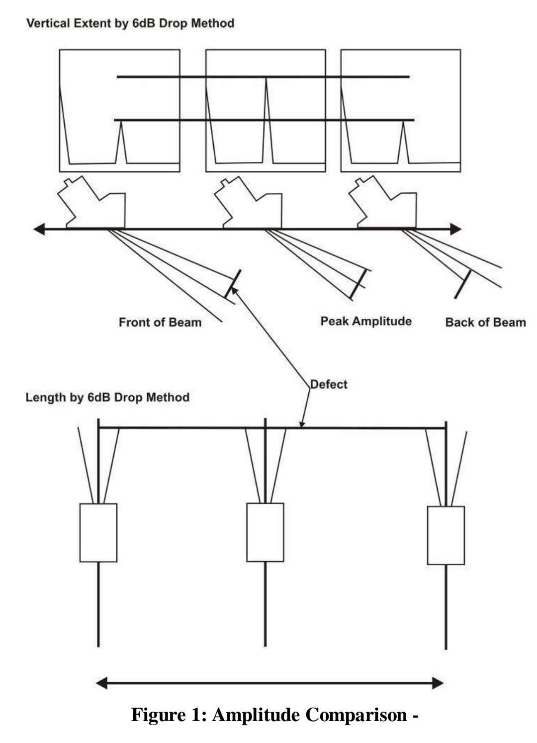
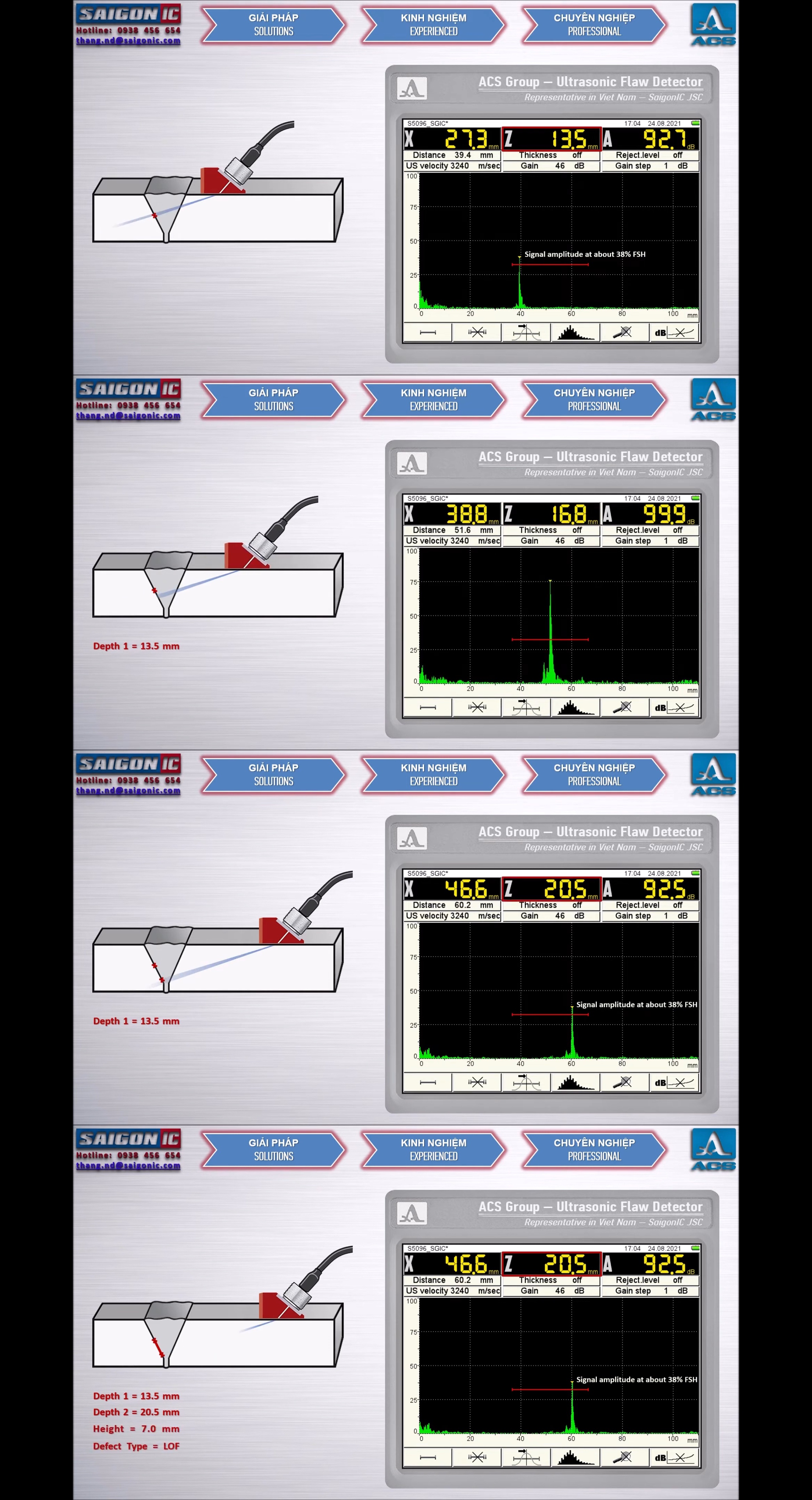
بعد از یافتن عیب و برای سایزینگ کردن 6dB از gain اسکن کم میکنیم یا به gain مرجع که در زمان DAC ترسیم کردیم می بریم سپس از تکنیک 6dB دراپ برای این کار استفاده می کنیم ، اول ماکزیمم ارتفاع سیگنال را بدست می آوریم اگر از صفحه بالا زده بود می توانیم با دستکاری gain آنرا طوری تنظیم کنیم که بتوانیم ماکزیمم سیگنال را پیدا کنیم سپس پراب را بصورت Lateral یا موازی با خط جوش به چپ یا راست می بریم تا ارتفاع آن سیگنالی که حداکثر آن را پیدا کردیم به نصف تقلیل یابد ، وسط پراب را با مداد یا گچ یا ... تا جوش ادامه می دهیم تا جوش را قطع کند سپس دو تا خط ابتدا و انتهای عیب را بهم متصل میکنیم تا طول عیب را بدست بیاوریم.
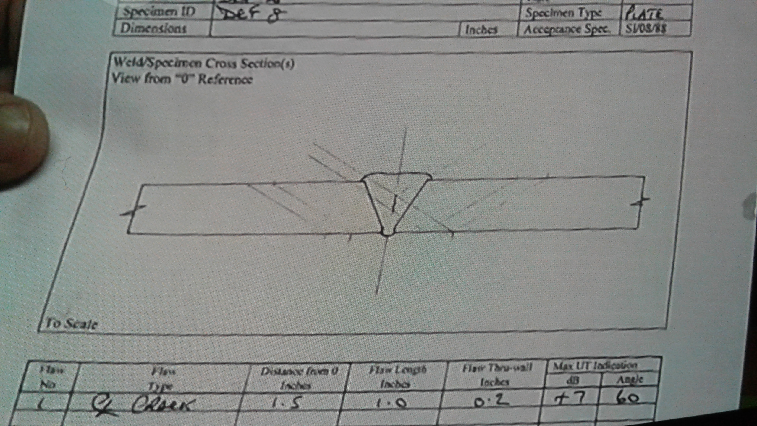
در شکل زیر عیب را پیدا کرده و سپس با خط کش فلزی Location عیب را روی جوش علامت میزند ، در زمان تست حتما سنتر جوش و صفر محلی که اسکن میکنید را مشخص نمایید و در جهت عقربه های ساعت اسکن را شروع کنید می توانید صفر UT را بعد از مارک کردن با سنبه نشان بزنید تا بعدها اگر مارک شما حذف شود اپراتور بعدی یا جوشکار Repair گیر بتواند از آن نقطه و طبق گزارش ثبت شده محل عیب را شناسایی کند.

تکنیک افت 6 دسیبل برای تعیین طول عیب البته اگر عیب از قطر پراب بیشتر باشد

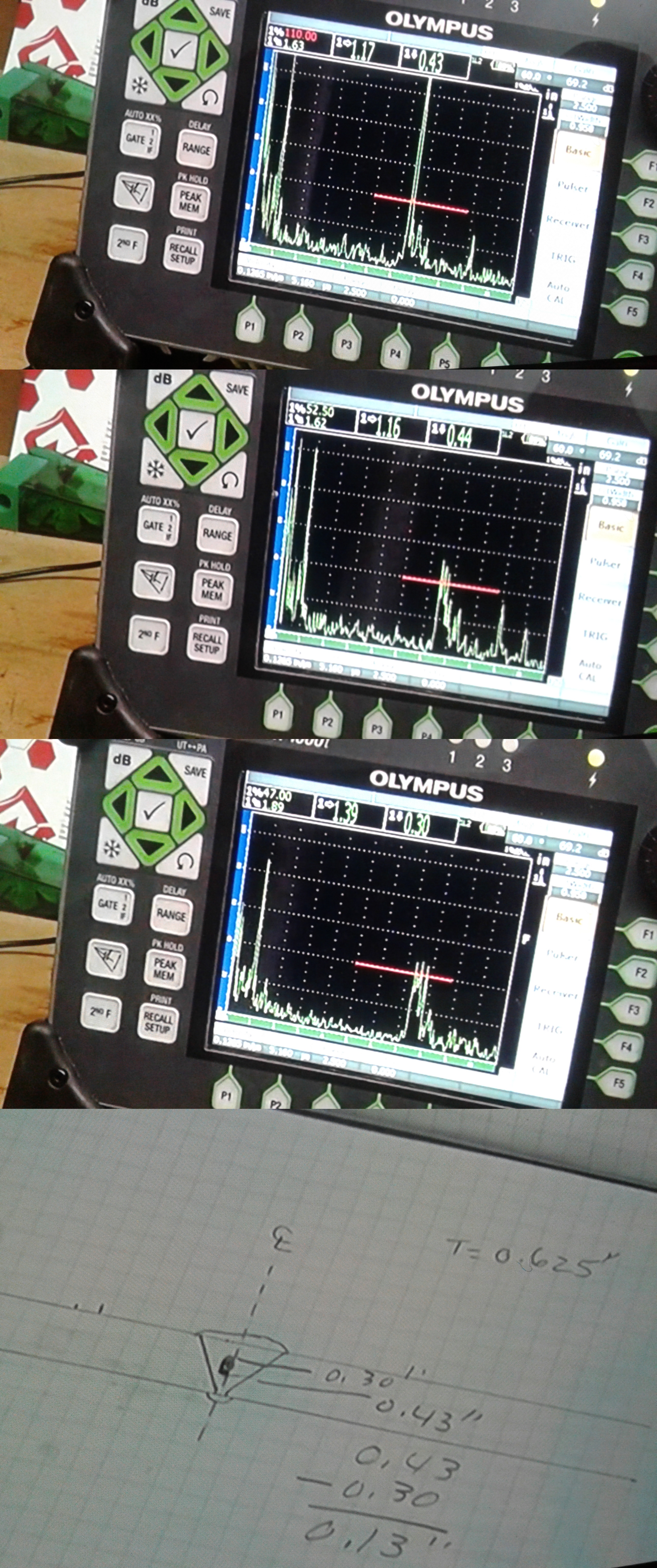
برای ضخامت عیب عدم ذوب دیواره های جانبی می توانید از تکنیک افت 20dB یا 10٪ ارتفاع استفاده کنید با عقب و جلو کردن پراب از سیگنال ماکزیمم
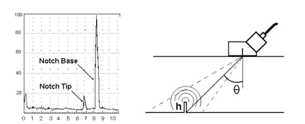
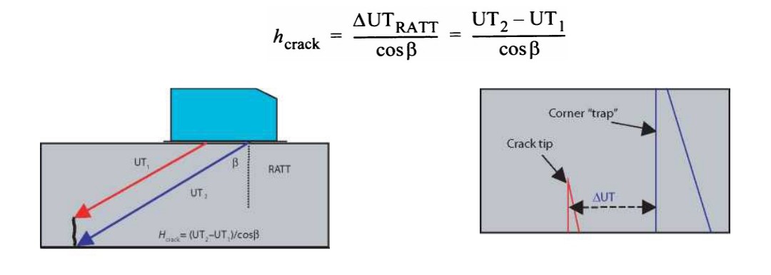
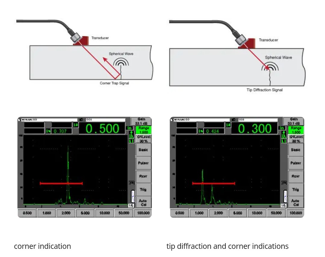
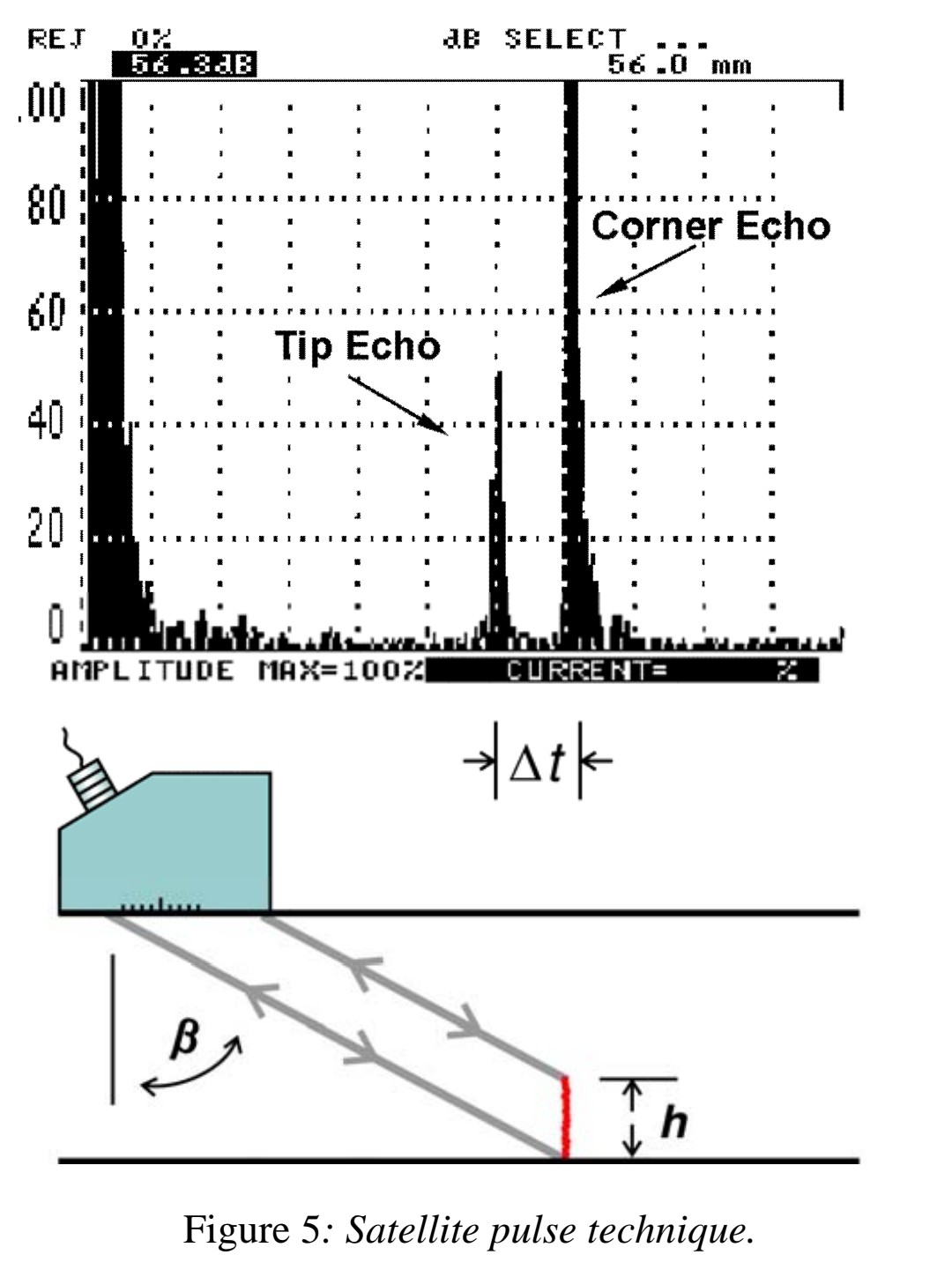
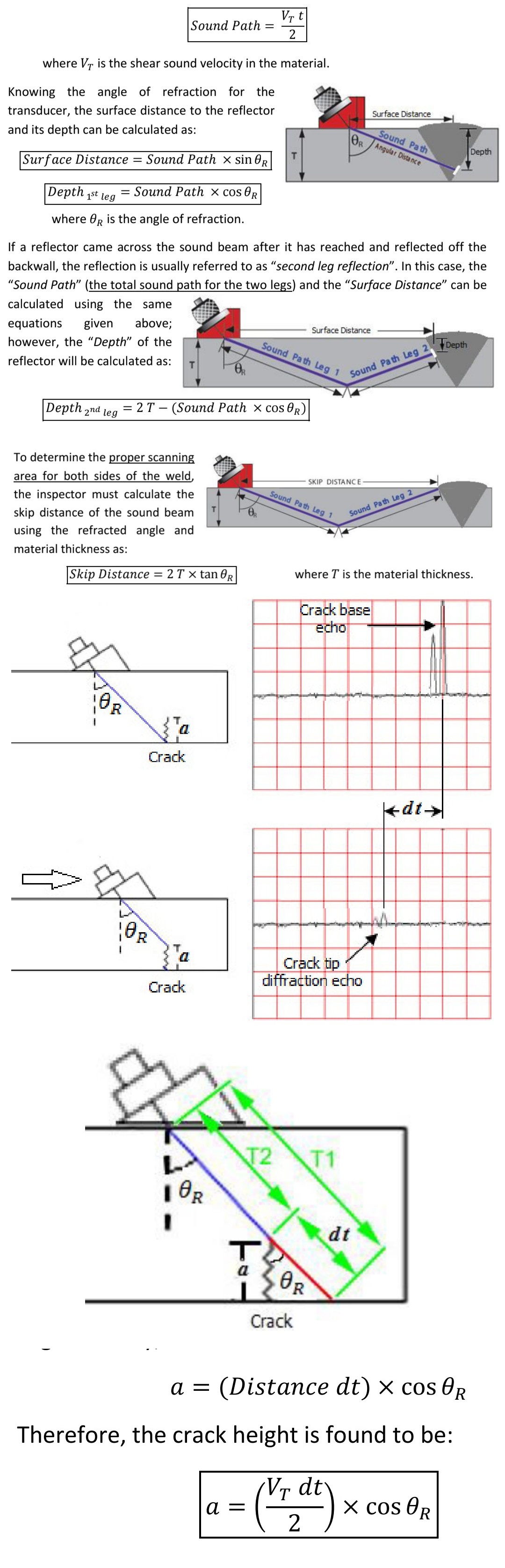
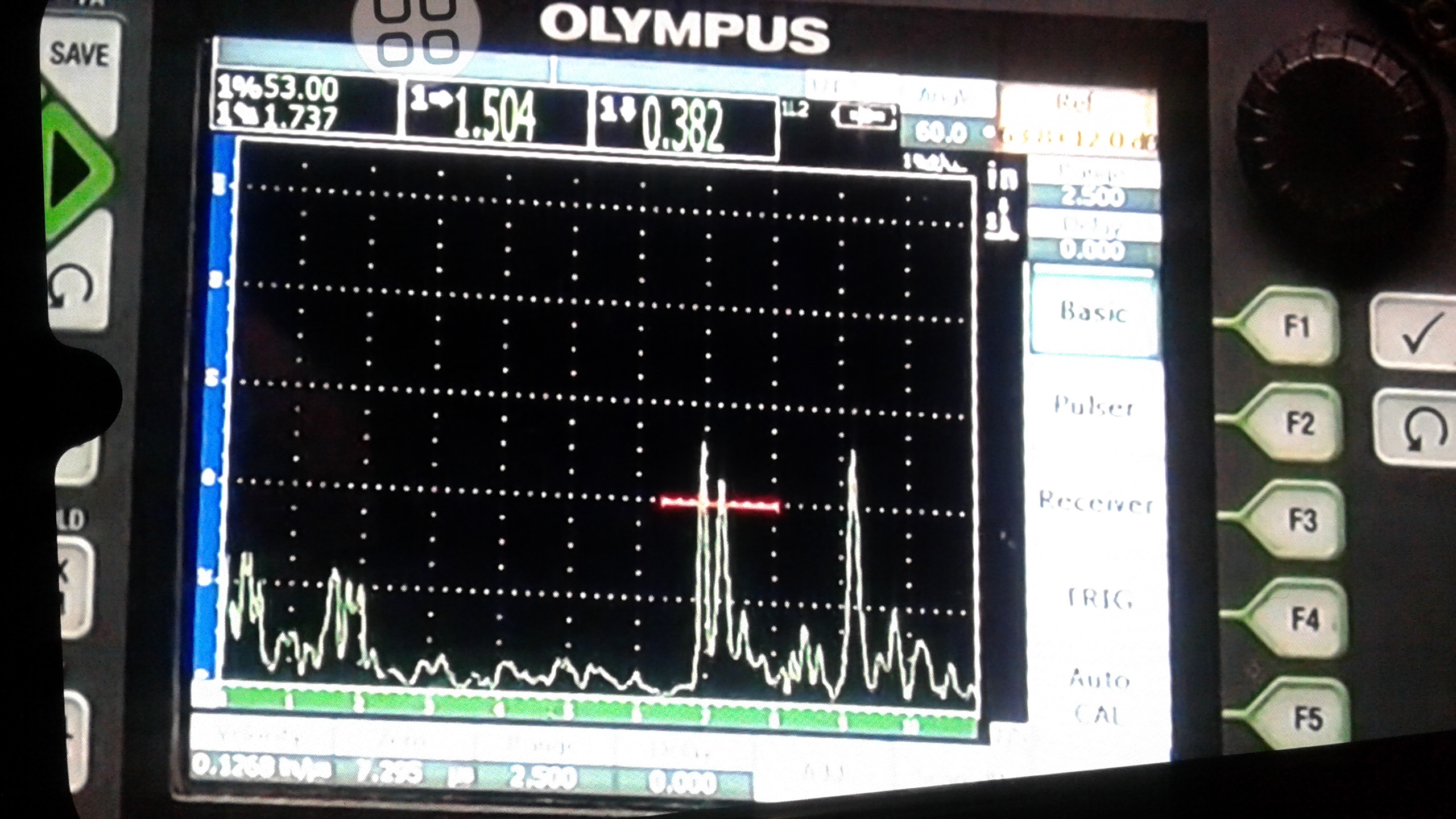
در شکل زیر اکوی ناچ دیده میشود زمانیکه دسته پرتو یا BEAM به بازتابنده اصابت میکند چون پایه ناچ از نظر سطح بازتابندگی وسعت بیشتری دارد تقریبا انرژی بیشتری را به پراب ارسال کرده توسط امپلی فایر تقویت شده و دامنه بیشتری را روی صفحه نمایش به ما نشان میدهد ولی نوک ناچ انرژی خیای کمتری را به پراب رسانده به همین علت دامنه کمتری دارد ولی چون مسیر کوتاه تری را طی کرده در ابتدا آمده ، فاصله بین دو اکو بستگی به عمق ناچ دارد.


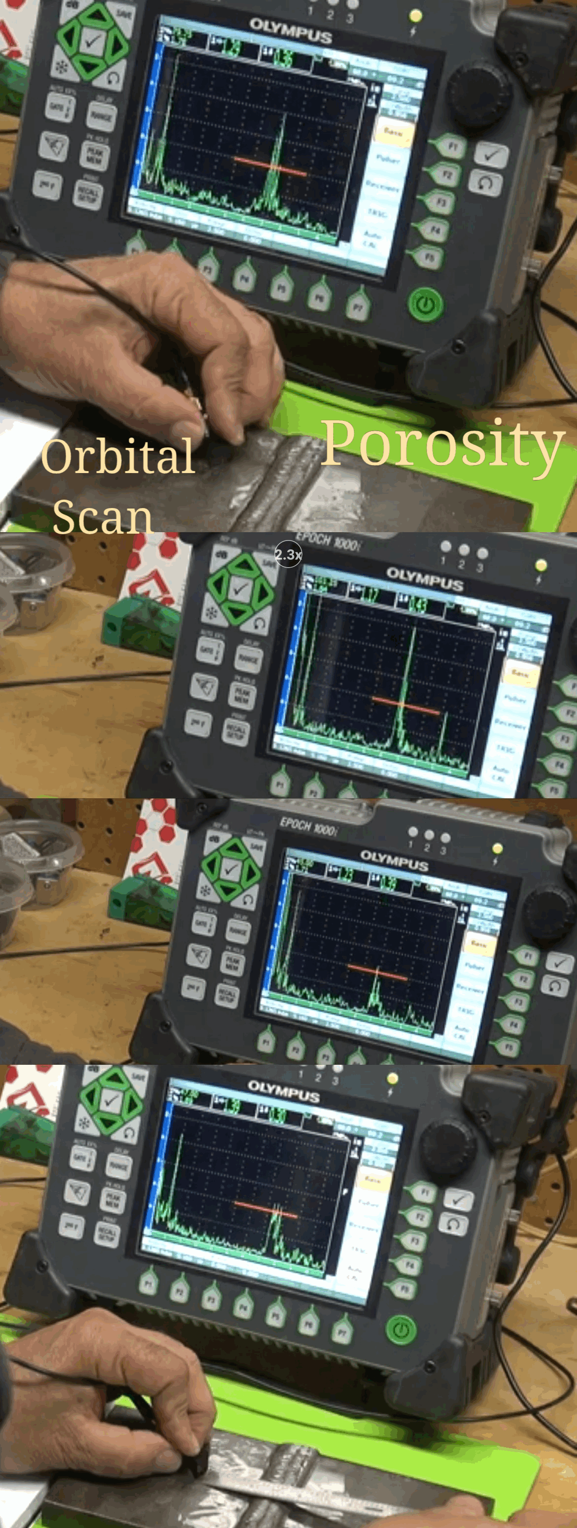
شکل زیر عیب LOP است . از دو سمت ، پراب را قرار داده و سیگنال با دامنه مشابهی دریافت نموده البته الان Gain روی 56dB که همان دسیبل مرجع است قرار داده شده ( بعد از پیدا کردن سیگنال و برای سایزینگ ) در قسمت آخر سایزینگ رو انجام داده فرضا زمانیکه با چپ بردن پراب ( البته موازی با محور جوش ) سیگنال اولیه از حدود 80 به 40 درصد ارتفاع خود رسیده وسط پراب را تا جایی که که خط جوش را قطع کند علامت زده ... پراب به هیچ عنوان کج نشود چون عیوب حفره ای نسبت به زاویه حساس هستند و دامنه بالایی را نشان می دهند دقیقا حرکت پراب موازی با جوش باشد مگر اینکه شما رفتار پراب برای تعیین عیوب صفحه ای یا حجمی را بخواهید متوجه شوید. پراب را در روی ضخامت 25 بلوک V1 و درست مقابل قرص پرسپکس ( قرار داده ) سیگنالی دریافت میکنید حال به سمت چپ و راست بروید ( قرص مثل یک عیب حفره ای عمل میکند ) یا کمی پراب را بچرخانی حدود 10 درجه رفتار اکو را ببینید.


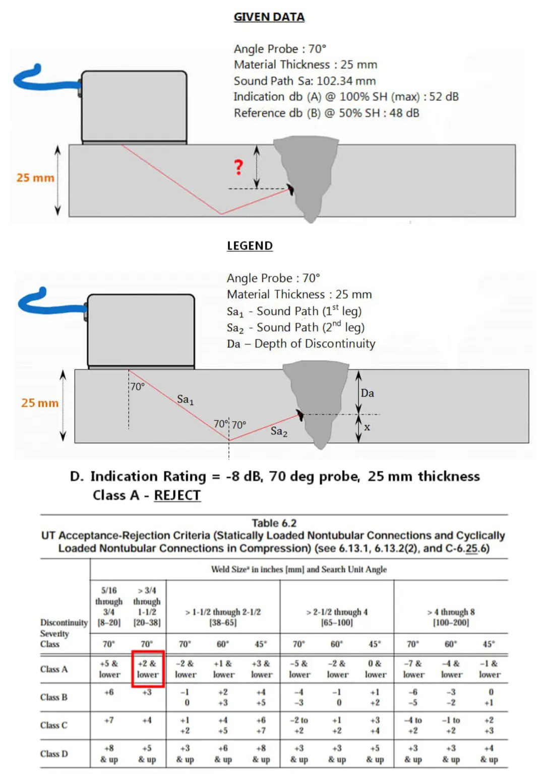
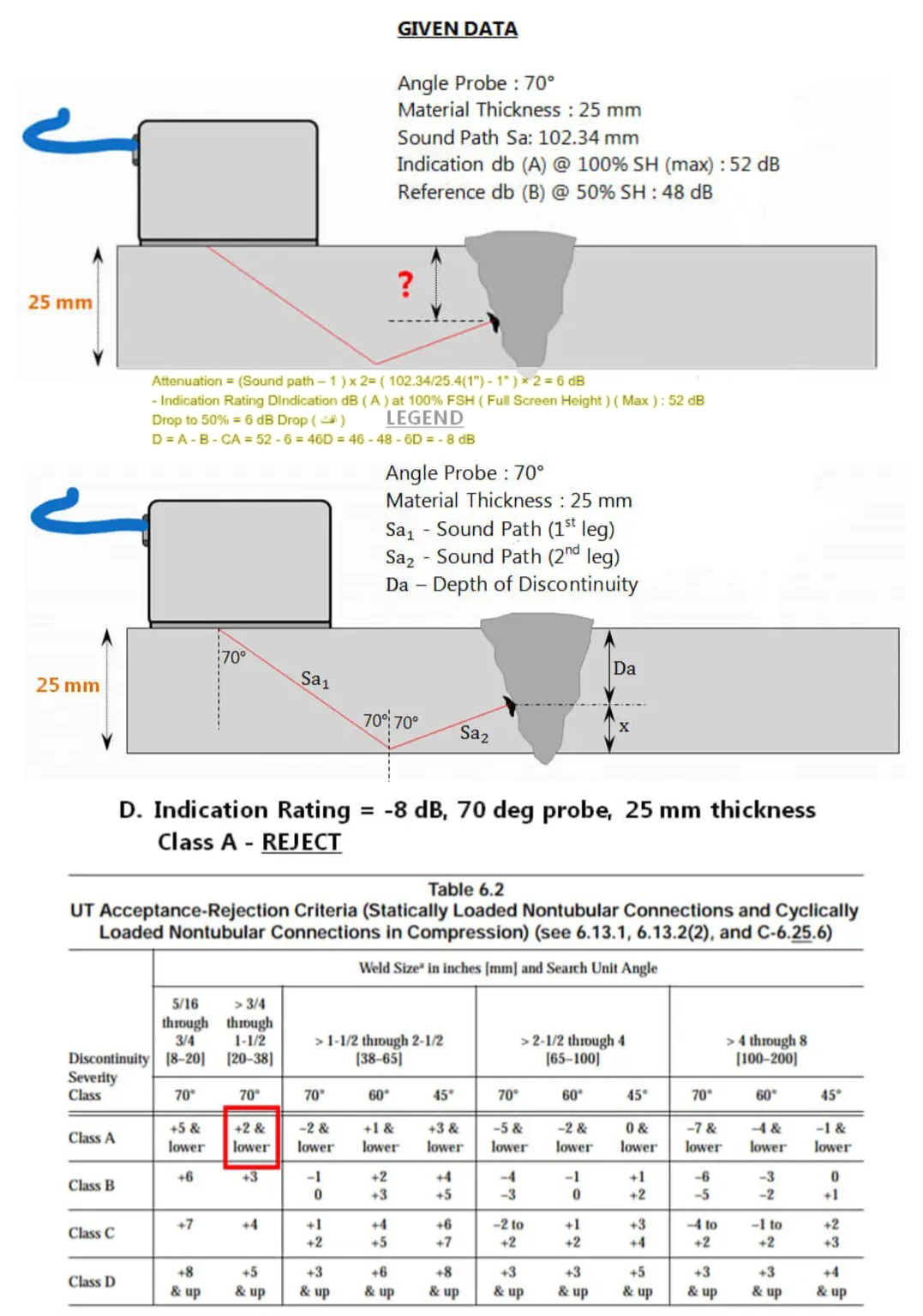
10^(2)÷(4×5٬920÷5٬000) = 21.1
Near Zone
Position an angle beam search unit on a calibration block, as shown in Fig. 3 so that indications from both the 1/2 and 3/4T holes give a 2:1 ratio of amplitudes between the two indications. Adjust the sensitivity(gain) so that the larger indication is set at 80% of full screen height(FSH). Without moving the search unit, adjust sensitivity(gain) to successively set the larger indication from 100% to 20% of full screen height, in 10% increments(or 2dB steps if a fine control is not available), and read the smaller indication at each setting. The reading shall be 50% of the larger amplitude, within 5% of FSH. The settings and readings shall be estimated to the nearest 1% of full screen. Alternatively, a straight beam search unit may be used on any calibration block that provides amplitude differences, with sufficient signal separation to prevent overlapping of the two signals.

این آزمون فقط خطی بودن نمایشگر (Screen Height Linearity) را بررسی میکند، نه عملکرد پراب یا حساسیت ماده.
کنترل خطی بودن دامنه
Amplitude Control Linearity
Position an angle beam search unit on a basic calibration block, as shown in Fig. 3 so that the indication from the 1/2T side-drilled hole is peaked on the screen. Adjust the sensitivity(gain) as shown in the following table. The indication shall fall within the specified limits. Alternatively, any other convenient reflector from any calibration block may be used with angle or straight beam search units.The settings and readings shall be estimated to the nearest 1% of full screen.

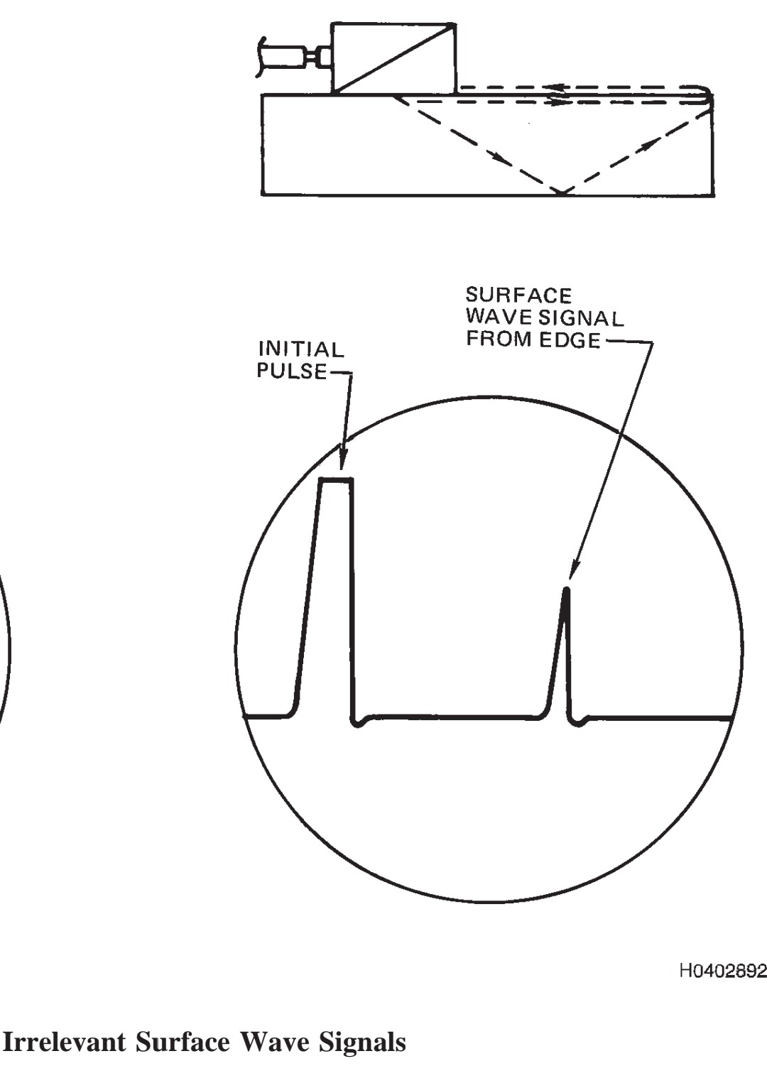
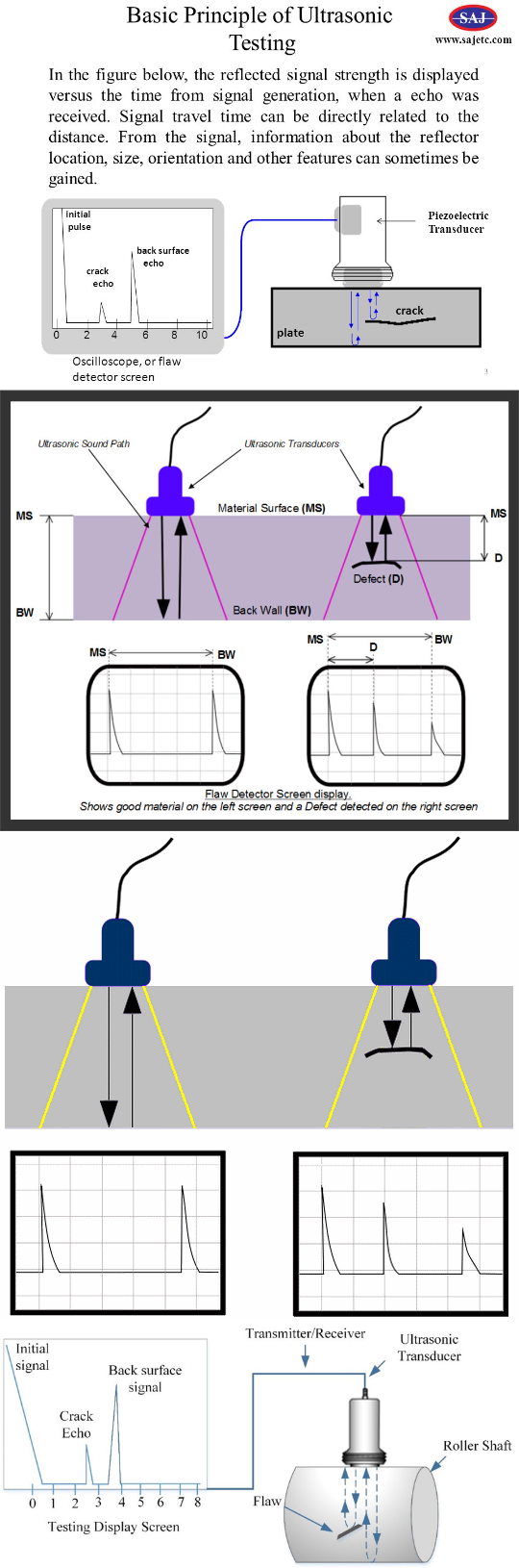
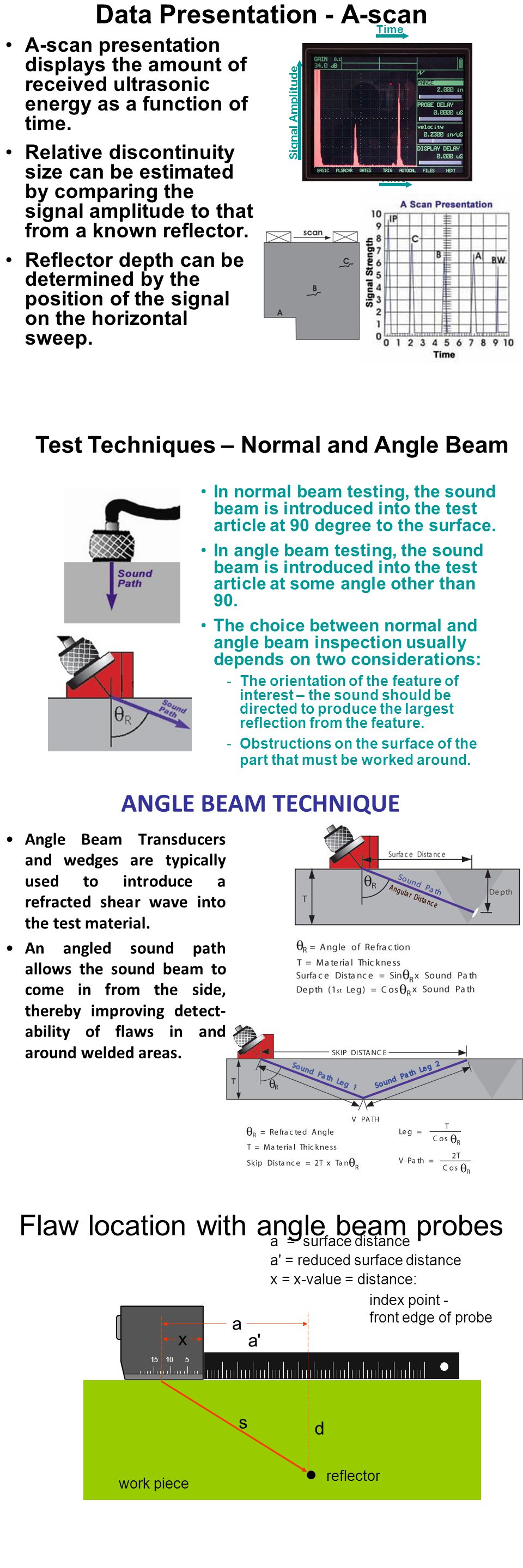
سیگنال اول IP یا Initial puls معرف منطقه مرده یا Dead zone است
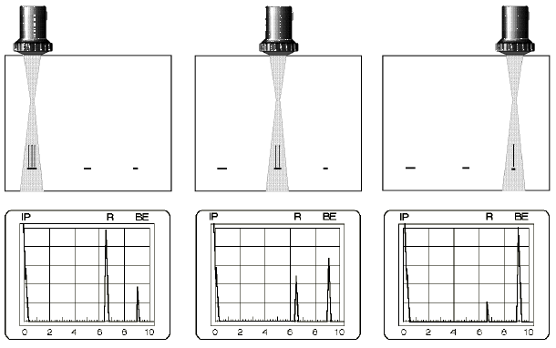
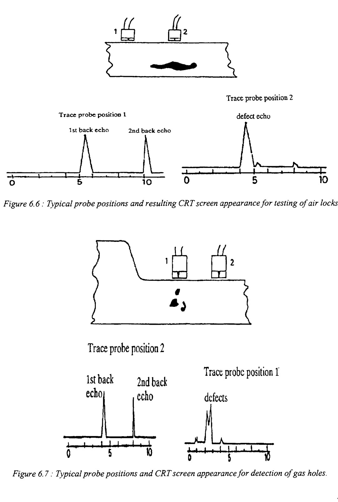
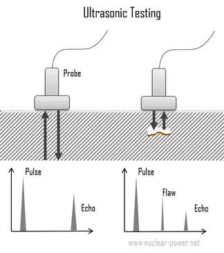
درصد کمی از صوت به عیب خورده و بیشترش به دیواره پشتی در نتیجه سیگنال Flaw که با حرف F نمایش داده شده ارتفاع کمتری نسبت به بک وال ( BACK WALL ECHO ) اول دارد
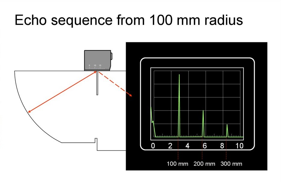
هر چه صوت مسیر بیشتری طی کند ( از پراب به داخل قطعه و از قطعه به پراب و N بار تکرار میشود ) سیگنال های بعدی در صفحه اسکن نسبت به قبل ضعیفتر شده و با ارتفاع کمتری نمایش داده می شوند
در بالا رنج دستگاه طوری تنظیم شده که دو بک وال در صفحه قابل مشاهده باشد در نتیجه اکوهای بعدی همون دو اکوی اول هستند ولی با تضعیف فواصل بینشون هم دوبرابر میشه
هر زمان بین بک وال اول و IP اکویی ظاهر شد بدانید در قطعه ناپیوستگی وجود دارد ... نبود بک وال را جدید بگیرید
در تست برای بررسی عیوب Lamenar حتما دو بکوال ( رنج روی دو ضخامت از قطعه ) را در صفحه ببینیم و بک وال اول را روی 50 تا 75 درصد FSH تنظیم کرده و بعد شروع به اسکن کنید برای اندازه گیری بعد عیوب بزرگتر از قطر پراب از تکنیک افت 6 دسیبل یا افت ارتفاع به 50 درصد صفحه استفاده کنید برای عیبی که خیلی کوچکتر از قطر پراب است از بیرون عیب جایی بکوال دیواره را دارید به سمت عیب بروید جایی که ارتفاع به نصف رسید لبه عیب است لذا لبه جلویی پراب یا Leading Edge را علامت بزنید

این بندها مهم هستند و در عمل چک نمی شوند !!!
ASME V, T-467.3.1
If any distance range point has moved on the sweep line by more than 10% of the distance reading or 5% of full sweep, whichever is greater, correct the distance range calibration and note the correction in the examination record. All recorded indications since the last valid calibration or calibration check shall be reexamined and their values shall be changed on the data sheets or re-recorded."
اگر هر نقطه ای از محدوده فاصله (نقطه کالیبراسیون) روی Sweep line (محور افقی صفحه)، بیش از ۱۰ درصد از مقدار فاصله خوانده شده یا ۵ درصد از کل پهنای Sweep ( رنج ) جابجا شده باشد (هر کدام که بیشتر است)، کالیبراسیون محدوده فاصله را اصلاح کنید و این اصلاح را در یادداشت های بازرسی قید نمایید. تمام نشانه های ثبت شده ای که از آخرین کالیبراسیون معتبر یا چک کالیبراسیون تا کنون ثبت شده اند، باید مجدداً بازرسی شده و مقادیر آنها در برگه های داده اصلاح یا دوباره ثبت شوند.»
یعنی سایزینگ عیوب نامعتبر است و می بایست دوباره چک شده و اصلاح شوند
ASME V, T-467.3.2
If any sensitivity setting has changed by more than 20% or 2 dB of its amplitude, correct the sensitivity calibration and note the correction in the examination record. If the sensitivity setting has decreased, all data sheets since the last valid calibration check shall be marked void and the area covered by the voided data shall be reexamined. If the sensitivity setting has increased, all recorded indications since the last valid calibration or calibration check shall be reexamined and their values shall be changed on the data sheets or re-recorded.
اگر هر تنظیمات حساسیتی (Gain یا dB) بیش از ۲۰ درصد یا ۲ دسیبل از دامنه (ارتفاع سیگنال) خود تغییر کرده باشد، کالیبراسیون حساسیت را اصلاح کنید و این اصلاح را در یادداشتهای بازرسی قید نمایید.
· اگر تنظیمات حساسیت کاهش یافته باشد (یعنی Gain کم شده): تمام برگههای داده از آخرین چک کالیبراسیون معتبر تا کنون، باید باطل (Void) اعلام شده و منطقهای که تحت پوشش آن دادههای باطل بوده، مجدداً بازرسی شود.
· اگر تنظیمات حساسیت افزایش یافته باشد (یعنی Gain زیاد شده): تمام نشانههای ثبتشده از آخرین کالیبراسیون یا چک کالیبراسیون معتبر تا کنون، باید مجدداً بازرسی شده و مقادیر آنها در برگههای داده اصلاح یا دوباره ثبت شوند.
۱. تلرانس حساسیت (Gain): حداکثر تغییر مجاز = ۲۰% ارتفاع دامنه یا ۲ دسیبل (هرکدام که زودتر به دست آید).
۲. تفاوت مهم بین کاهش و افزایش Gain:
· کاهش Gain (حساسیت کمتر): یعنی سیگنالها کوچکتر دیده شدهاند. در این حالت، تمام برگههای داده باطل میشوند و باید کل منطقه دوباره اسکن شود (چون ممکن است عیوب کوچک از دست رفته باشند).
· افزایش Gain (حساسیت بیشتر): یعنی سیگنالها بزرگتر دیده شدهاند. در این حالت، فقط اندازهگیریها (سایزینگ) اشتباه است، پس باید دوباره سایزینگ کنید و مقادیر را اصلاح کنید (نیازی به اسکن مجدد کل منطقه نیست).
۳. نکته ترکیبی: اگر همزمان هم جابجایی نقطه (طبق T-467.3.1) و هم تغییر Gain (طبق T-467.3.2) داشتید، باید هر دو بند را جداگانه اعمال کنید و سختگیرانهترین تصمیم را بگیرید.
حساسیت یعنی بزرگنمایی یا تقویت سیگنال
کاهش Gain = عیوب ریز گم میشوند = کل کار باطل و اسکن مجدد.
افزایش Gain = عیوب بزرگتر دیده میشوند = فقط سایزینگ مجدد.
-- اگر Gain کم شود ← برگه ها باطل و اسکن مجدد (چون ممکن است عیوب از دست رفته باشند).
-- اگر Gain زیاد شود ← فقط سایزینگ مجدد (چون عیوب دیده شده اند ولی اندازه اشتباهی دارند).
Height = 50
Upper limit (20% ) 50 + 20% = 60%
Lower limit ( 20% ) 50 - 20% = 40%
Upper limit ( 2dB ) 10²/²⁰ × 50 = 62.9 %FSH
Lower limit ( 2dB ) 10-²/²⁰ × 50 = 39.7 %FSH
20% Or 2dB
Acceptance limit : 39.7% ~ 60%
ASME V ARTICLE 4 NONMANDATORY APPENDIX D

.
1.What technique should be used to scan weld joints when a distance-amplitude technique is specified?
A. Angle beam search unit in both parallel and transverse directions.
B. Straight beam examination only
C. Only manual scanning techniques
D. Only automated scanning techniques
2.What is the minimum beam angle that should be selected for the angle beam technique?
A. 30 degrees
B. 45 degrees.
C. 60 degrees
D. 90 degrees
3.What must be recorded during the ultrasonic examination?
A. Only the scan plan
B. Only the indication data
C. All specified information including scan plan and instrument settings.
D. Only the final display processing levels
4.What is required if there is a change in an essential variable of the written procedure?
A. No action is required
B. Requalification of the written procedure is required.
C. Only a review of the procedure is needed
D. The procedure can be used as is
5.What should be noted in the examination report for inaccessible welds?
A. The welds cannot be examined from any side.
B. The welds can be examined with a straight beam
C. The extent of the limit coverage
D. The welds are not important
6.What is the purpose of performing a straight beam examination before angle beam examinations?
A. To locate any reflectors that can limit the angle beam examination.
B. To calibrate the angle beam search unit
C. To determine the angle of the beam
D. To record the final display processing levels
7.What type of search units should be used for weld metal overlay cladding examinations?
A. Single element, straight beam search units
B. Dual element, straight beam search units using an angled pitch-catch technique.
C. Only automated search units
D. Only manual search units
8.What is the maximum number of inactive elements allowed within an aperture?
A. 1 element for every 8 elements
B. 1 element for every 12 elements
C. 1 element for every 16 elements.
D. No inactive elements are allowed
9.What should be done if the examination personnel change during the ultrasonic examination?
A. No action is required
B. The system calibration must be confirmed.
C. The examination should be stopped
D. The procedure can be used as is
10.What is the purpose of the calibration block in ultrasonic examinations?
A. To provide a reference for system calibration.
B. To record the examination results
C. To determine the angle of the beam
D. To clean the examination surface
11.What is the purpose of the angle beam technique in ultrasonic examination?
A. To examine weld joints in both parallel and transverse directions.
B. To perform straight beam examinations only
C. To calibrate the ultrasonic equipment
D. To clean the examination surface
12.What should be included in the written procedure for ultrasonic examination?
A. Only the scan plan
B. Only the indication data
C. All requirements listed in Table T-421.
D. Only the final display processing levels
13. For similar metal weld calibration blocks, which P-Number groups are considered equivalent?
A. P-Nos. 1, 2, 3, and 4
B. P-Nos. 1, 3, 4, 5A through 5C, and 15A through 15F.
C. P-Nos. 1 through 10
D. All P-Numbers are equivalent
14.For dissimilar metal welds, how is the calibration block material selected?
A. Based on the material on the side from which the examination will be conducted.
B. Based only on the weaker material
C. Based only on the stronger material
D. Any material with equivalent thickness can be used
15. If the examination is conducted from both sides of a dissimilar metal weld, what is required for calibration reflectors?
A. A single set of reflectors in one material is sufficient
B. Calibration reflectors shall be provided in both materials.
C. No calibration reflectors are required
D. Only the material with higher acoustic impedance needs reflectors
16. When is a transfer correction required?
A. When the block material is not of the same product form or has not received the same heat treatment.
B. Whenever the ambient temperature exceeds 25°C
C. For every examination without exception
D. Only when using angle beam transducers
17. Before fabrication of the calibration block, what is the acceptance criterion for the block material?
A. No indications are allowed anywhere in the block
B. Areas containing an indication exceeding the remaining back-wall reflection shall be excluded from the beam paths.
نواحیای که شامل یک نشانه (پژواک) بیش از پژواک پشتوارهی باقیمانده باشند، باید از مسیرهای پرتو حذف شوند.
C. Only surface indications are acceptable
D. All indications must be recorded but can be used
18. What examination must be performed on the calibration block material prior to fabrication?
A. Angle beam examination from both directions
B. Straight beam examination of the entire block material.
C. Only surface inspection with a straight beam
D. No examination is required before fabrication
19. What are the acceptable sources for fabricating a calibration block according to the cladding requirements?
A. Nozzle dropout, component prolongation, or material of the same specification, product form, and heat treatment.
B. Only material from the same heat number
C. Only production off-cuts with no heat treatment
D. Any material with equivalent acoustic properties
20. If the cladding method used on the component is unknown or impractical, how may the calibration block be clad?
A. The block must be left unclad
B. Cladding may be deposited by the manual method.
C. Cladding must be deposited by automatic strip method
D. The examination shall be performed without a calibration block
21. For a clad component, what is the specified tolerance for the cladding thickness on the calibration block?
A. ± 1/16 in. (1.5 mm)
B. ± 1/8 in. (3 mm).
C. ± 1/4 in. (6 mm)
D. ± 1/2 in. (12 mm)
22. When the parent materials on opposite sides of a weld are clad by different P-, A-, or F-numbers and the examination is conducted from only one side, how is the calibration block clad?
A. With both cladding types on separate blocks
B. With the same P-, A-, or F-number and method used on the side of the weld from which the examination is conducted.
C. With the stronger material only
D. With the weaker material only
23. What is the requirement for the calibration block if the component weld has been heat treated at the time of examination and the block contains welds (other than cladding)?
A. The block must be heat treated to a higher temperature
B. The block must be air-cooled only
C. The block shall receive the same heat treatment as the component weld.
D. No heat treatment is required for the block
24. For materials with a diameter greater than 20 inches (500 mm), what alternative to a curved block is permitted?
A. No alternative is permitted
B. A flat basic calibration block may be used.
C. Only a block with the exact same diameter is acceptable
D. A block with any curvature is acceptable
25. How many curved blocks for pipe less than 20" are required ?
A. 4 blocks
B. 6 blocks.
C. 8 blocks
D. 10 blocks
26. When examining from a convex surface by the straight beam contact technique, what alternative is permitted?
A. Nonmandatory Appendix G may be used
B. Nonmandatory Appendix J may be used
C. No alternative is permitted
D. Only curved blocks may be used
27. In the figure, what is the basic ratio value at the lower limit for curved surfaces?
A. 0.9.
B. 1.5
C. 2.69
D. 4.32
28. what is the basic ratio value at the upper limit for curved surfaces?
A. 0.9
B. 1.5.
C. 2.69
D. 4.32
50 - Based on AWS D1.1 UT Requirements
1. What is the primary purpose of using a couplant in ultrasonic testing of welds?
A) To clean the surface
B) To protect the transducer from wear
C) To eliminate the air gap and allow sound transmission.
D) To increase the signal frequency
2. Which type of wave is primarily used for angle-beam testing of groove welds per AWS D1.1?
A) Longitudinal waves
B) Shear waves.
C) Surface waves
D) Lamb waves
3. During angle-beam testing, what does the term "index point" refer to?
A) The center of the transducer crystal
B) The point on the wedge where sound enters the test material.
C) The location of the maximum signal on the screen
D) The reference point for sensitivity calibration
4. What is the acceptable tolerance for the refracted angle of an angle-beam search unit during verification?
A) ±1°
B) ±2°.
C) ±3°
D) ±5°
5. Which of the following is the correct frequency range for angle-beam transducers used in weld inspection?
A) 1.0 – 1.5 MHz
B) 2.0 – 2.5 MHz.
C) 3.5 – 4.0 MHz
D) 5.0 – 6.0 MHz
6. What is the minimum active area required for a straight-beam transducer used for base metal testing?
A) 0.25 in²
B) 0.5 in².
C) 0.75 in²
D) 1.0 in²
7. Why is the reject (suppression) control required to be turned off during UT calibration and testing?
A) It reduces battery life
B) It may alter amplitude linearity and invalidate results.
C) It increases noise level
D) It changes the sound velocity
8. What is the maximum scanning speed allowed for manual UT of welds?
A) 4 in/sec
B) 6 in/sec.
C) 8 in/sec
D) 10 in/sec
9. Which type of reference block is commonly used for both distance and sensitivity calibration in AWS D1.1 UT?
A) RC block
B) IIW type block.
C) DS block only
D) Step wedge block
10. What type of reflector is explicitly prohibited for calibration purposes?
A) Side-drilled hole
B) Flat-bottom hole
C) Corner reflector.
D) Notch
11. What does the "attenuation factor" account for in the UT indication rating formula?
A) Couplant loss
B) Sound energy loss due to material and path length.
C) Transducer wear
D) Instrument drift
12. In the indication rating formula for instruments with gain in dB, which variable represents the reference level?
A) a
B) b.
C) c
D) d
13. How is the length of a discontinuity typically determined when its amplitude exceeds the Class D rating?
A) By measuring the 3 dB drop points
B) By measuring the 6 dB drop points.
C) By measuring the 10 dB drop points
D) By visual measurement only
14. What is the minimum allowable range of the gain control (attenuator) linearity per AWS D1.1?
A) 20 dB
B) 40 dB
C) 60 dB.
D) 80 dB
15. How often must the horizontal linearity of the UT instrument be requalified?
A) Monthly
B) Every two months.
C) Quarterly
D) Annually
16. After how many hours of use must the internal reflections of each search unit be verified?
A) 10 hours
B) 20 hours
C) 40 hours.
D) 80 hours
17. How often must each angle-beam search unit be checked for flatness, index point, and angle?
A) After each shift
B) After each 8 hours of use.
C) After each 40 hours of use
D) Weekly
18. What is the maximum allowable thickness range for which Part F UT procedures are directly applicable?
A) 1/4 in to 4 in
B) 5/16 in to 8 in.
C) 1/2 in to 10 in
D) 3/8 in to 12 in
19. If a weld thickness exceeds 8 in, which annex provides alternative UT procedures?
A) Annex H
B) Annex O.
C) Annex G
D) Annex E
20. What is the primary scanning requirement for butt joint welds?
A) Test from one side only
B) Test from each side of the weld axis.
C) Test from the cap surface only
D) Test using only 70° angle
21. What is the recommended NDT method to supplement UT for detecting piping porosity in ESW/EGW welds?
A) Magnetic particle testing
B) Liquid penetrant testing
C) Radiographic testing.
D) Eddy current testing
22. What is the maximum allowable variation in instrument response due to supply voltage change?
A) ±0.5 dB
B) ±1 dB.
C) ±2 dB
D) ±3 dB
23. What is the required display type for UT instruments per AWS D1.1?
A) B-scan
B) C-scan
C) A-scan rectified video trace.
D) Time-of-flight diffraction display
24. What is the primary purpose of the RC resolution reference block?
A) Sensitivity calibration
B) Distance calibration
C) Checking transducer and instrument resolution.
D) Attenuation measurement
25. What does the term "scanning level" refer to in UT weld inspection?
A) The sensitivity level used for initial calibration
B) The sensitivity level increased above reference level to detect discontinuities.
C) The gain setting used for length measurement
D) The noise floor level
26. What should be done if a laminar discontinuity in the base metal interferes with normal weld scanning?
A) Reject the base metal
B) Use an alternate scanning procedure and report it.
C) Ignore it and continue testing
D) Reduce gain and retest
27. What is the correct procedure for distance calibration in shear wave mode?
A) Use position A on IIW block
B) Use position D on IIW block and adjust for indications at 4 in and 8 in
C) Use position G on IIW block
D) Use straight-beam transducer only
28. Which position on the IIW block is used for sensitivity (amplitude) calibration in shear wave mode?
A) Position A
B) Position B
C) Position C
D) Position D
29. What is the minimum resolution requirement for the transducer and instrument combination?
A) Resolve two holes
B) Resolve three holes in RC block.
C) Resolve four holes
D) No resolution requirement
30. What is the maximum amplitude of internal reflections allowed from a search unit above reference level?
A) No reflections allowed
B) Reflections allowed only below reference level
C) Reflections allowed only if less than 50% screen height
D) Screen area beyond 1/2 in sound path shall be free of any indication above reference level.
31. When must recalibration be performed during UT testing?
A) At the start of each day only
B) After each 2-hour interval or any change in circuitry.
C) At the end of each shift
D) Only when the transducer is changed
32. What should be the back reflection height for straight-beam calibration of base metal?
A) 25% – 50%
B) 50% – 75%.
C) 75% – 100%
D) 100% full screen
33. Which of the following is NOT a valid couplant material per AWS D1.1?
A) Glycerin
B) Cellulose gum and water
C) Light machine oil (on calibration blocks)
D) Petroleum jelly.
34. What is the purpose of the "X" line marked on the weldment?
A) To indicate the weld start point
B) To provide a reference for discontinuity location perpendicular to weld axis.
C) To mark the heat-affected zone
D) To indicate the welding direction
35. What is the purpose of the "Y" line marking?
A) To identify weld orientation
B) To identify Face A and assist in distance measurements.
C) To mark the root face
D) To identify the cap pass
36. What is the maximum allowable undercut depth for cyclically loaded members in primary tension?
A) 0.010 in [0.25 mm].
B) 1/32 in [1 mm]
C) 1/16 in [2 mm]
D) 1/8 in [3 mm]
37. For cyclically loaded tension welds, Class C discontinuities in the top or bottom quarter of weld thickness must be rejected if length exceeds:
A) 3/4 in [20 mm].
B) 1 in [25 mm]
C) 2 in [50 mm]
D) 3 in [75 mm]
38. Class A discontinuities (large) shall be rejected regardless of:
A) Location only
B) Length only
C) Both length and location.
D) Depth only
39. What is the required qualification interval for gain control (attenuator) calibration?
A) Monthly
B) Every two months.
C) Every three months
D) Every six months
40. What does the term "sound-path distance" in Tables 8.2 and 8.3 refer to?
A) Material thickness
B) Distance from the index point to the reflector.
C) Weld length
D) Plate width
41. For statically loaded structures, Class D discontinuities are:
A) Always rejected
B) Accepted regardless of length or location.
C) Rejected if longer than 2 in
D) Require further evaluation
42. What is the maximum allowable piping porosity diameter in fillet welds per AWS D1.1 visual criteria?
A) 1/16 in [1.5 mm]
B) 3/32 in [2.5 mm].
C) 1/8 in [3 mm]
D) 5/32 in [4 mm]
43. What must be done if a weld repair is performed?
A) Only visual inspection is required
B) The repaired area must be retested ultrasonically and results recorded.
C) No retesting is required
D) Only magnetic particle testing is needed
44. What type of certification is required for an individual approving UT procedures for advanced ultrasonic systems?
A) AWS CWI
B) NDT Level III.
C) ASNT Level II
D) PE license
45. What is the minimum experience requirement for an NDT Level III in advanced ultrasonic systems?
A) 3 months
B) 6 months.
C) 1 year
D) 2 years
46. What is the maximum allowable scanning speed for automated or manual UT per AWS D1.1?
A) 4 in/sec
B) 6 in/sec.
C) 8 in/sec
D) 10 in/sec
47. What does the "6 dB drop" method determine in discontinuity evaluation?
A) The depth of the discontinuity
B) The length of the discontinuity.
C) The type of discontinuity
D) The orientation of the discontinuity
48. Which scanning pattern is used for transverse discontinuities in unground welds?
A) Pattern A
B) Pattern B
C) Pattern D
D) Pattern E.
49. What is the required procedure when a UT indication remains on the display as the search unit is moved?
A) Ignore it
B) Refer to 8.13.1 or 8.13.2.1 for evaluation.
C) Reject the weld immediately
D) Reduce gain and re-evaluate
50. What is the primary advantage of using a 70° angle beam for thin materials?
A) Better penetration depth
B) More perpendicular sound path
C) Shorter sound path for same thickness.
D) Lower attenuation in steel
"For thinner sections, higher angles (e.g., 70°) provide a shorter sound path for the same thickness, reducing attenuation and improving signal-to-noise ratio."
1. In a UT test on a weld, the operator records the following:
· Indication level (a) = 42 dB
· Reference level (b) = 38 dB
· Attenuation factor (c) = 1.2 dB
The instrument uses gain in dB.
What is the Indication Rating (d) ?
A) 2.8 dB
B) 4.8 dB
C) 3.0 dB.
D) 5.0 dB
2. A shear wave UT inspection is performed on a 1.5 in [38 mm] thick plate. The sound-path distance to a reflector is 8 in [200 mm]. According to the attenuation factor rule for US Customary units, what is the value of factor "c"?
A) 7.0
B) 14.0.
C) 3.5
D) 8.0
3. Using an instrument with attenuation in dB (not gain), the following values are recorded:
· Reference level (b) = 48 dB
· Indication level (a) = 52 dB
· Attenuation factor (c) = 2.5 dB
What is the Indication Rating (d) ?
A) –-6.5 dB.
B) –-1.5 dB
C) +6.5 dB
D) +1.5 dB
4. During a UT scan, a discontinuity produces an indication with a rating more serious than Class D. The operator moves the transducer and notes that the signal drops to 50% of its peak height at two positions. The distance between these two transducer centerline locations is measured as 1.2 in [30 mm]. what is the recorded length of this discontinuity?
A) 0.6 in [15 mm]
B) 1.2 in [30 mm].
C) 2.4 in [60 mm]
D) 0.3 in [7.5 mm]
5. According to Table 8.3 (cyclically loaded tension), a Class C discontinuity is located in the middle half of the weld thickness and its length is measured as 2.5 in [64 mm]. What is the correct disposition per the code?
A) Accept, because Class C in middle half has no length limit
B) Reject, because it exceeds the 2 in [50 mm] limit for middle half.
C) Accept, because Class C is always acceptable regardless of length
D) Reject only if it is also in the top quarter
6. During UT calibration, the operator adjusts the gain so that the signal from the 0.060 in hole on the IIW block reaches 40% of full screen height.
This signal level is recorded as the:
A) Scanning level
B) Reference level (b).
C) Indication level (a)
D) Attenuation factor (c)
7. The reference level (b) is established at 48 dB on an instrument with gain in dB. The weld being inspected is part of a cyclically loaded tension connection, and the sound-path distance to the farthest volume of the weld is 8 in [200 mm]. According to the code, what total scanning level (dB) should the operator use during the scan?
سطح مرجع (b) روی یک دستگاه با گین بر حسب دسیبل، روی عدد ۴۸ دسیبل تنظیم شده است. برای اسکن جوش، اپراتور باید مطابق جدول ۸.۳، برای یک مسافت صوت به طول ۸ اینچ [۲۰۰ میلیمتر]، حساسیت را افزایش دهد. سطح اسکن (تنظیم کل دسیبل) در حین اسکن چقدر خواهد بود؟
A) 48 dB
B) 73 dB
C) 83 dB.
D) 93 dB
8. A UT instrument with attenuation in dB shows a reference level (b) of 52 dB. The operator increases attenuation to 60 dB to bring a reflector signal to reference height. What is the Indication Rating (d) if the attenuation factor (c) is 1.5 dB?
یک دستگاه فراصوت با تضعیف بر حسب دسیبل، سطح مرجع (b) را ۵۲ دسیبل نشان میدهد. اپراتور تضعیف را به ۶۰ دسیبل افزایش میدهد تا سیگنال یک بازتابنده به ارتفاع مرجع برسد. اگر ضریب تضعیف (c) برابر ۱.۵ دسیبل باشد، ایندیکیشن ریتینگ (d) چقدر خواهد بود؟
A) +6.5 dB
B) -6.5 dB
C) +10.5 dB
D) –10.5 dB
9. Which of the following correctly describes the relationship between scanning level and reference level for UT of welds?
کدام یک از گزینه های زیر رابطه بین سطح اسکن و سطح مرجع را برای آزمون فراصوت جوشها به درستی توصیف میکند؟
A) Scanning level is always lower than reference level
B) Scanning level = reference level + additional dB per Table 8.2 or 8.3
C) Scanning level is set using the RC block
D) Scanning level is independent of material thickness

10. The reference level sensitivity (b) is established using the 0.060 in hole on the IIW block. If the operator changes to a different IIW block with the same hole size but different material attenuation, what must be done?
حساسیت سطح مرجع (b) با استفاده از سوراخ ۰.۰۶۰ اینچی روی بلوک IIW تنظیم میشود. اگر اپراتور به بلوک IIW دیگری با همان اندازه سوراخ ولی با تضعیف ماده متفاوت تغییر دهد، چه کاری باید انجام دهد؟
A) No change is needed
B) Re-establish reference level (b) with the new block.
C) Increase scanning level by 6 dB
D) Use a different transducer frequency
"Other portable blocks may be used, provided the reference level sensitivity for instrument/search unit combination is adjusted to be the equivalent of that achieved with the IIW type block."
نکته: این بخش صراحتاً میگه هر بلوک جایگزین باید معادل بلوک IIW تنظیم بشه.
11. In a UT test on a cyclically loaded tension connection (thickness = 1 in, 70° probe), the following are recorded:
· Reference level (b) = 44 dB (gain instrument)
· Indication level (a) = 50 dB
· Attenuation factor (c) = 2.3 dB
What is the Indication Rating (d) and the correct disposition?
A) d = +3.7 dB → Reject .
B) d = –3.7 dB → Accept
C) d = +6.7 dB → Accept
D) d = –6.7 dB → Reject
12. When using an instrument with attenuation in dB, the formula for Indication Rating (d) is:
هنگام استفاده از دستگاهی با تضعیف بر حسب دسیبل، فرمول محاسبهٔ ایندیکیشن ریتینگ (d) کدام است؟
A) d = a-b -c
B) d = b-a-c.
C) d = a + b + c
D) d = b + a-c
"Instruments with gain in dB: a-b-c = d"
"Instruments with attenuation in dB: b-a-c = d"

13. According to the code, the gain control (attenuator) of the UT instrument must be adjustable in discrete steps of:
A) 0.5 or 1 dB
B) 1 or 2 dB.
C) 2 or 3 dB
D) 5 or 10 dB
14. What is the minimum required range for the calibrated gain control (attenuator) per AWS D1.1?
A) 40 dB
B) 50 dB
C) 60 dB.
D) 80 dB
15. The accuracy of the attenuator settings shall be within:
A) ±0.5 dB
B) ±1 dB.
C) ±2 dB
D) ±3 dB
16. What is the minimum active area required for a straight-beam transducer?
A) 1/4 in² [161 mm²]
B) 1/2 in² [323 mm²].
C) 3/4 in² [484 mm²]
D) 1 in² [645 mm²]
17. What is the maximum allowable width-to-height ratio for an angle beam transducer crystal?
A) 1.0:1.0
B) 1.1:1.0
C) 1.2:1.0.
D) 1.5:1.0
18.. Which of the following angles is NOT listed as a proper angle for angle-beam search units?
A) 45°
B) 60°
C) 70°
D) 80°.
19. The marking on each angle-beam search unit must clearly indicate the nominal angle of refraction, frequency, and:
A) Wedge material
B) Index point.
C) Crystal thickness
D) Cable length
20. If an angle-beam search unit produces a beam at 68° instead of the nominal 70°, is this acceptable per code?
A) Yes, because tolerance is ±2.°
B) No, tolerance is only ±1°
C) No, any deviation is rejected
D) Yes, if re-calibrated on site
1. When a discontinuity indication appears on the screen, what does the operator do to determine the "Indication Level" value?
A) Measure the screen height of the echo without any changes
B) Use the calibrated gain control to adjust the echo to a horizontal reference level and record the dB reading.
C) Compare the echo to a previous weld's echo
D) Record the depth of the discontinuity directly from the screen
2. In the US customary measurement system, how is the attenuation correction factor calculated from the sound-path distance?
A) Subtract 25 mm from the distance and multiply by 0.08
B) Divide the distance by 2 and subtract 1 inch
C) Subtract 1 inch from the distance and multiply the result by 2.
D) Add 1 inch to the distance and divide by 2
3. When using SI units, which calculation gives the correct attenuation factor?
A) Subtract 1 mm from the sound-path and multiply by 2
B) Subtract 1 inch from the sound-path and multiply by 0.08
C) Multiply the sound-path directly by 2
D) Subtract 25 mm from the sound-path and multiply by 0.08.
4. After calculating the attenuation factor, what is the proper rounding rule?
A) Round up to the next whole number
C) Round to two decimal places
B) Round to one decimal place; if less than 0.05 round down, if 0.05 or greater round up.
D) Keep the exact value with no rounding
5. For an ultrasonic instrument that uses gain control (dB), the Indication Rating is determined by which relationship?
A) Indication Level minus Reference Level minus Attenuation Factor.
B) Reference Level minus Indication Level minus Attenuation Factor
C) Indication Level plus Reference Level divided by Attenuation Factor
D) Reference Level plus Indication Level minus Attenuation Factor
6. For an instrument that uses attenuation control instead of gain, how is the Indication Rating calculated?
A) Indication Level minus Reference Level minus Attenuation Factor
B) Reference Level minus Indication Level minus Attenuation Factor.
C) Reference Level plus Indication Level minus Attenuation Factor
D) Reference Level minus Indication Level plus Attenuation Factor
7. Once the Indication Rating number is obtained, how must it be rounded?
A) To the nearest 0.5 dB
B) To the nearest whole dB; decimals under 0.5 go down, 0.5 and over go up.
C) To one decimal place
D) No rounding is performed
8. What two factors determine whether a weld discontinuity is accepted or rejected?
A) Its depth and its type and indication rating
B) Its location , its orientation , its Length
C) Its amplitude and its Rating
D) Its Indication Rating and its length.
9. Which discontinuities must be included on the test report?
A) Every discontinuity found in the weld
B) Only those that are unacceptable, except for Fracture Critical welds where acceptable ratings within 6 dB of the rejection limit must also be recorded.
C) Only discontinuities longer than 1 inch
D) Only discontinuities with a rating higher than 10 dB
10. How should a rejected area be physically marked on the welded joint?
A) Marking depth and rating written on base metal
B) Marking Rating , depth and type
C) Marking length , depth and rating written on base metal.
D) Marking the letter "R"(Rejected ) next to the weld
11. After a weld is repaired due to unacceptable UT results, what is the required next step?
A) The repaired area must be ultrasonically retested and the results documented
B) No additional testing is needed
C) Only visual inspection is sufficient
D) The entire weld must be cut out and replaced
12. When retesting a repaired area and using the original report form, how should the new results be identified?
A) By starting a completely new form
C) By overwriting the old results
B) By adding a prefix R Such as R1,R2,...
D) By attaching a separate note
13. What special consideration is required when performing UT on complete joint penetration groove welds that have steel backing?
A) The backing must be removed before testing
B) Only longitudinal wave testing is allowed
C) The procedure must account for potential true reflections from the base metal–backing interface
D) The procedure must account for potential false reflections from the base metal–backing interface.
14. What is the minimum information required on a report for a weld that is found acceptable?
A) Full welding procedure specifications
B) All calibration records and the operator's signature
C) identify the weld, the operator's signature, and a statement of acceptability.
D) Complete discontinuity lengths and ratings
15. After the project is completed, what is the contractor's responsibility regarding UT reports?
A) Keep all reports for at least 10 years
B) Submit all completed report forms to the Owner
C) Destroy all records immediately
D) Keep them indefinitely for future reference
16. What is the Contractor's obligation regarding UT reports?
1) Only reports of acceptable welds shall be submitted to the Owner
2) All UT reports, including those showing rejected welds (prior to repair), shall be submitted along with acceptable welds.
3) Reports of unacceptable welds shall be submitted only if requested by the Owner
4) The Contractor is only required to submit final reports (after repair), and pre-repair reports need not be submitted


1. A device that transforms electrical pulses into mechanical and vice versa utilizes:
a. Snell's law
b. piezoelectric principles.
c. mode conversion principles
d. none of the above
2. Another name for Fresnel zone is:
a. Fraunhoferzone
b. near field.
c. far field
d. Torrid zone
3. Attenuation is a:
a. test display characteristic
b. test material parameter
c. transducer characteristic.
d. form of testing
4. “25 million cycles per second” can also be stated as:
a. 25 kHz
b. 2500 kHz
c. 25 MHz.
d. 25 nHz
5. Moving a transducer over a test surface either manually or automatically is referred to as:
a. scanning.
b. attenuating
c. angulating
d. resonating
6. A term used in ultrasonic to express the rate at which sound wave pass trough various substances is:
a. frequency
b. velocity
c. wavelength
d. pulse length
7. The indication on the instrument display that represents the far boundary of the material being tested is called:
a. hash
b. the initial pause
c. the main bang
d. the back surface reflection.
8. Sweep range echo amplitude display on CRT is an illustration of a typical for:
a. A-scan presentation.
b. B-scan presentation
c. C-scan presentation
d. D-scan presentation
9. Plan View mapping showing variation of thickness is an illustration of a typical:
a. A-scan presentation
b. B-scan presentation
c. C-scan presentation.
d. D-scan presentation
10.Cross-section of weld display on CRT is an illustration of a typical:
a. A-scan presentation
b. B-scan presentation.
c. C-scan presentation
d. D-scan presentation
11. An ultrasonic testing technique in which the transducer element is not parallel to the test surface is called:
a. angle beam testing.
b. immersion testing
c. contact testing
d. through-transmission testing
12. Most commercial ultrasonic testing is accomplished using frequencies between:
a. 1 and 25 kHz
b. 1 and 1 000 kHz
c. 0.2 and 25 MHz.
d. 15 and 100 MHz
13. In an A-scan presentation, the horizontal base line represents:
a. the amount of reflected ultrasonic sound energy
b. the distance traveled by the transducer.
c. the elapsed time or distance
d. none of the above
14. The process of comparing an instrument or device with a standard is called:
a. angulation
b. calibration.
c. attenuation
d. correlation
15. Another name for a compressional wave is:
a. Lamb wave
b. shear wave
c. longitudinal wave.
d. transverse wave
16. Another name for Rayleigh waves is:
a. shear waves
b. longitudinal waves
c. transverse waves
d. surface waves.
17. A material used between the face of a transducer and the test surface to permit or improve the transmission of ultrasonic vibrations from the transducer to the material being tested is called:
a. a wetting agent
b. a couplant.
c. an acoustic transmitter
d. a lubricant
18. Ultrasonic testing of material where the transducer is in direct contact with the material being tested may be:
تست فراصوت مادهای که در آن ترانسدیوسر (پراپ) در تماس مستقیم با مادهی تحت تست است، میتواند به شکل ........ باشد
a. straight beam testing
b. surface wave testing
c. angle beam testing
d. all of the above.
19. The velocity of surface waves is approximately ___________ the velocity of shear waves in the same material
a. two times
b. four times
c. 1/2
d. 9/10.
20. Under most circumstances, which of the following frequencies would result in the best resolving power? ( Resolution )
در اغلب شرایط، کدام یک از فرکانسهای زیر منجر به بهترین قدرت تفکیک (رزولوشن) میشود؟
a. 1 MHz
b. 5 MHz
c. l0MHz
d. 25MHz.
21. In contact testing, the entry surface indication is sometimes referred to as:
در روش تماسی، سیگنال نشاندهندهی سطح ورود صوت، گاهی اوقات با چه نامی خوانده میشود؟
a. the initial pulse.
b. the back reflection
c. the skip distance
d. the scan path
22. When the motion of the particles of a medium is parallel to the direction of propagation, the wave being transmitted is called a:
a. longitudinal wave.
b. shear wave
c. surface wave
d. lamb wave
23. When the motion of the particles of a medium is transverse to the direction of propagation, the wave being transmitted is called a:
هنگامی که حرکت ذرات یک محیط، عمود بر جهت انتشار باشد، به موجی که منتقل میشود، چه میگویند؟
a. longitudinal wave
b. shear wave.
c. surface wave
d. Lamb wave
24. A piezoelectric material can:
a. convert a longitudinal beam to a shear wave
b. convert an mechanical energy to electrical energy.
c. create ionization in a test specimen
d. produce sound waves in a coaxial cable
25. The velocity of sound waves is primarily dependent on:
a. the pulse length
b. the angle of incidence
c. the material, material thickness, and UT frequency (time between
signals on the display)
d. none of the above.
26. The primary purpose of reference blocks is to:
هدف اصلی از بلوکهای مرجع (Reference Blocks) چیست؟
a. aid the operator in obtaining maximum back reflections
b. obtain the greatest sensitivity possible from an instrument
c. obtain a common reproducible signal.
d. none of the above
هدف اصلی از بلوکهای مرجع (Reference Blocks) در تست فراصوت، به دست آوردن یک سیگنال قابل تکرار و یکسان (Common Reproducible Signal) است.
27. When testing by the surface wave method, patches of oil or dirt on the surface may:
هنگام تست با روش امواج سطحی، لکههای روغن یا کثیفی روی سطح ممکن است .......
a. block the progress of all sound.
b. attenuate the sound
c. have no effect on the test
d. cause both an attenuation of sound and indications on the screen.
28. The piezoelectric material in the transducer:
ماده پیزوالکتریک درون ترانسدیوسر (پراپ) .......
a. converts electrical energy into sound
b. converts electrical energy into mechanical energy.
c. eliminates the signal-to-noise energy
d. produces high speed electrons in metals
29. The angle of incidence is:
زاویه تابش (برخورد) عبارت است از:
a. greater than the angle of reflection
b. less than the angle of reflection
c. equal to the angle of reflection.
d. not related to the angle of reflection
30. The gradual loss of sonic energy as the ultrasonic vibrations travel through the material is referred to as:
از دست رفتن تدریجی انرژی صوتی در حین عبور ارتعاشات فراصوت از درون ماده، چه نامیده میشود؟
a. reflection
b. refraction
c. reproducibility
d. attenuation.
31. When testing a plate, increasing the frequency of an ultrasonic longitudinal wave results in:
هنگام تست یک ورق ، افزایش فرکانس یک موج طولی فراصوت، چه نتیجه ای دارد؟
a. an increase in its velocity
b. a decrease in its velocity
c. no change in its velocity.
d. a reversal in its velocity
32. The depth of a discontinuity cannot be determined when using the:
عمق یک ناپیوستگی زمانی که از روش ........ استفاده میشود، قابل تعیین نیست.
a. straight beam testing method
b. through-transmission testing method.
c. angle beam testing method
d. immersion testing method
33. "100 000 cycles per second" can be written:
a. 0.1 kHz
b. 10 kHz
c. 100 kHz.
d. 100 MHz
34. The phenomenon whereby an ultrasonic wave changes direction when the wave crosses a boundary between materials with different velocities is called :
به پدیدهای که در آن یک موج فراصوت وقتی از مرز بین دو ماده با سرعتهای متفاوت عبور میکند، تغییر جهت میدهد، چه گفته میشود؟
a. refraction.
b. reflection
c. penetration
d. rarefaction
35. In a test where the transducer is not perpendicular to the inspection surface, the angle of incidence is equal to :
در آزمایشی که ترانسدیوسر عمود بر سطح بازرسی نیست، زاویه تابش برابر است با:
a. the angle of refraction
b. the angle of reflection.
c. the shear wave angle
d. half the shear wave angle
36. Ultrasonic waves that travel along the surface of a material and whose particle motion is elliptical are called:
به امواج فراصوتی که در امتداد سطح یک ماده حرکت میکنند و حرکت ذرات آنها به صورت بیضوی است، چه گفته میشود؟"
a. shear waves
b. transverse waves
c. longitudinal wave
d. Rayleigh waves.
37. The interference field near the face of a transducer is often referred to as the:
به میدان تداخلی (ناحیهای که امواج در آن با هم تداخل میکنند) در نزدیکی سطح ترانسدیوسر، اغلب چه گفته میشود
a. Fresnel zone.
b. acoustic impedance
c. exponential field
d. phasine zone
38. When the incident angle is chosen to be between the first and second critical angles, the ultrasonic wave mode within the part will be a:
زمانی که زاویه تابش بین زاویه بحرانی اول و دوم انتخاب شود، مد موج فراصوت در داخل قطعه به صورت ...... خواهد بود.
a. longitudinal wave
b. shear wave.
c. surface wave
d. Lamb wave
39. The formula used to calculate the angle of refraction within a material is called :
فرمولی که برای محاسبه زاویه شکست درون یک ماده به کار میرود، چه نام دارد؟
a. Fresnel's law
b. Fraunhofer's law
c. Snell's law.
d. Lamb’s law
40. In a material with a given velocity, when frequency is increased, the wavelength will:
در یک ماده با سرعت معین، وقتی فرکانس افزایش مییابد، طول موج چه تغییری میکند؟
a. not be affected
b. increase
c. decrease.
d. double
1. Shear waves do not propagate in:
a. Solids
b. Gases
c. Liquids.
d. Both B and C are correct
2. Which of the following waves is only able to travel through a thin section of material?
کدام یک از امواج زیر فقط قادر به عبور از یک مقطع نازک از ماده است؟
a. A longitudinal wave
b. A shear waves
c. A surface wave
d. A lamb wave.
3. Artificial flaws can be produced by using:
عیوب مصنوعی می توانند با استفاده از .... ایجاد شوند :
a. Side drilled holes
b. Flat bottom holes
c. Edge notches
d. All of the above.
4. The ability to locate discontinuities that are close together within the material is called:
توانایی تشخیص ناپیوستگیهایی که درون ماده به هم نزدیک هستند، چه نام دارد؟
a. Resolution.
b. Sensitivity
c. Effectiveness
d. Phase delay
5. What is the material called that is used to improve the transmission of ultrasonic sound energy from the transducer into the part?
مادهای که برای بهبود انتقال انرژی صوت فراصوت از ترانسدیوسر به قطعه به کار میرود، چه نام دارد؟
a. Gel
b. Goo
c. Couplant.
d. Contact paste
6. The ability to locate a small discontinuity is called:
توانایی تشخیص یک ناپیوستگی کوچک، چه نام دارد؟
a. Resolution
b. Sensitivity.
c. Wavelength
d. Frequency
7. When a wave encounters an interface at an oblique angle, what takes place at the interface due to the different sound velocities of the two materials?
هنگامی که یک موج با زاویه مایل به یک فصل مشترک برخورد میکند، به دلیل سرعتهای متفاوت صوت در دو ماده، چه پدیدهای در فصل مشترک رخ میدهد؟
a. Attenuation
b. Refraction.
c. Beam spread
d. Beam impedance
8. The combined effect of scattering and absorption is called:
اثر ترکیبی پراکندگی و جذب (انرژی صوتی) چه نام دارد؟
a. Shear factor
b. Propagation
c. Attenuation.
d. Impedance
9. The sound energy or ultrasonic beam is more uniform in the:
انرژی صوتی یا پرتو فراصوت در کدام ناحیه یکنواختتر است؟
a. Far field zone.
b. Near field zone
c. Interface between the transducer and plastic wedge
d. Band along the central axis
10. The measure of how a signal from a defect compared to other background reflections is called:
معیاری که نشان میدهد سیگنال حاصل از یک عیب در مقایسه با سایر بازتابهای زمینه (نویز) چگونه است، چه نام دارد؟
a. Acoustic impedance
b. Signal to noise ratio.
c. Refraction
d. Reflection
توی صفحه نمایش دستگاه فراصوت، همیشه یک سری سیگنالهای ریز و بیربط (نویز) وجود داره که از ساختار ماده یا امواج مزاحم میان. وقتی یک عیب واقعی توی قطعه باشه، یک سیگنال (پژواک) ازش میاد.
نسبت سیگنال به نویز یعنی مقایسهی قد سیگنال عیب با قد نویزهای زمینه. هرچقدر این نسبت بزرگتر باشه، تشخیص عیب راحتتره.
مثلاً اگه سیگنال عیب ۱۰ برابر بلندتر از نویز باشه، نسبت SNR خوبه. اگه سیگنال عیب با نویز قاطی بشه، تشخیص عیب سخت میشه
11. Some transducers are specifically fabricated to be:
بعضی از ترانسدیوسرها به طور خاص برای چه کاری ساخته میشوند؟
a. Better transmitters’
b. Better receivers’
c. Used in high temperature applications
d. All of the above.
12. The active element of most acoustic transducers used today is:
عنصر فعال (ماده مولد موج) در بیشتر ترانسدیوسرهای صوتی امروزی چیست؟
b. Lithium
b. Piezoelectric ceramic.
c. Sulfide
d. Quartz
عنصر فعال (همون کریستال) در بیشتر ترانسدیوسرهای امروزی از سرامیک پیزوالکتریک (مثل PZT - تیتانات زیرکونات سرب) ساخته میشه. سرامیکها نسبت به کوارتز طبیعی، راندمان بالاتری در تولید و دریافت امواج فراصوت دارن و راحتتر شکل داده میشن.
13. The area in front of a transducer where there are extensive fluctuations in the sound field is called the:
ناحیهای در جلوی ترانسدیوسر که در آن نوسانات شدیدی در میدان صوتی وجود دارد، چه نامیده میشود؟
a. Far field zone
b. Surface field zone
c. Near field zone.
d. Phase shift zone
14. In the transverse or shear wave, the particles:
در موج عرضی (برشی)، ذرات محیط چگونه حرکت میکنند؟
a. Move in an elliptical pattern
b. Oscillate at a right angle to the direction of wave propagation.
c. Oscillate parallel to the direction of wave propagation
d. Do not actually move
15. Within a given material, the speed of sound:
در یک ماده معین، سرعت صوت چگونه است؟
a. Is constant.
b. Decreases with distance from the transducer
c. Increases with distance from the transducer
d. None of the above
16. When an ultrasound wave passes through an interface between two materials at an oblique angle, and the materials have different indices of refraction, it produces:
هنگامی که یک موج فراصوت با زاویه مایل از فصل مشترک بین دو ماده با ضریب شکست متفاوت عبور میکند، چه امواجی تولید میشود؟
a. Reflected waves
b. Refracted waves
c. Interface waves
d. Both A and B.
17. Acoustic impedance is identified by the letter:
a. Z.
b. I
c. V
d. P
18. In order to have a reasonable chance at detecting a discontinuity, the reflective surface of the discontinuity must have a dimension that is at least as long as ________ wavelength.
برای اینکه شانس معقولی برای تشخیص یک ناپیوستگی داشته باشیم، سطح بازتابکننده ناپیوستگی باید حداقل به اندازهی ........ طول موج، بعد (اندازه) داشته باشد.
a. One-half.
b. One
c. Two
d. One-quarter
19. Couplant displaces the__________ and makes it possible to get more sound energy into the test specimen.
کوپلنت .... را جابهجا میکند و باعث میشود انرژی صوتی بیشتری وارد نمونهtest شود.
a. Surface rust
b. Surface blemishes
c. Sound energy
d. Air.
20. Beam spread is greater when using:
واگرایی پرتو (Beam Spread) زمانی که از کدام نوع ترانسدیوسر استفاده میشود، بیشتر است؟
a. High frequency transducers
b. Low frequency transducers.
c. Angle beam transducers
d. Larger diameter transducers
فرکانس با نصف زاویه واگرایی رابطه عکس دارد. K.V / f.D
21. Which type of screen presentation displays a profile or cross sectional view of the test specimen?
کدام نوع نمایش صفحهای، نمای جانبی (پروفایل یا مقطع عرضی) از قطعهی تحت تست را نشان میدهد؟
a. A-scan
b. B-scan.
c. C-scan
d. All of the above
22. Which type of screen presentation displays a plan-type view of the location and size of the test specimen features?
کدام نوع نمایش صفحهای، نمای سطحی (Plan-type view) از موقعیت و اندازه ویژگیهای قطعهی تحت تست را نشان میدهد؟
a. A-scan
b. B-scan
c. C-scan.
d. All of the above
23. Resolution generally increases:
قدرت تفکیک (Resolution) معمولاً در چه صورتی افزایش مییابد؟
a. With increased depth of a defect
b. With a decrease in the transducer frequency
c. When the transducer diameter is reduced
d. With an increase in transducer frequency.
24. The material of the reference standard used to setup for a flaw inspection:
مادهی استاندارد مرجعی که برای تنظیم (کالیبره کردن) بازرسی عیوب استفاده میشود، باید چگونه باشد؟
a. Can be made from any material as long as the velocity is the same
b. Should be the same material being inspected.
c. Must have the same impedance values as the base material
d. Can only be used once
25. When a longitudinal wave encounters an interface between two material with different acoustic impedances, what occurs when the angle of incidence is 90 degrees?
هنگامی که یک موج طولی به فصل مشترک بین دو ماده با امپدانس آکوستیکی متفاوت برخورد میکند، وقتی زاویه تابش ۹۰ درجه باشد، چه اتفاقی میافتد؟
a. Reflection.
b. Refraction
c. Mode conversion
d. Reflection and refraction
26. Which of the following would make a good couplant?
a. Water
b. Oil
c. Glycerin
d. All of the above.
27. The act of evaluating and adjusting the precision and accuracy of the measurement equipment is called:
عمل ارزیابی و تنظیم دقت و صحت تجهیزات اندازهگیری، چه نامیده میشود؟
a. Standardization
b. Calibration.
c. Accuracy
d. Tuning
28. As frequency increases, sound tends to:
با افزایش فرکانس، صوت تمایل به ........ پیدا میکند.
a. Become more compressed
b. Scatter more from large or course grain structure.
c. Convert to a different wave mode
d. Become more penetrating
به دلیل کاهش طول موج، امواج بیشتر از ساختار دانههای درشت پراکنده میشوند
29. The first critical angle describes the condition where the:
زاویه بحرانی اول، وضعیتی را توصیف میکند که در آن:
a. The angle of the refracted longitudinal wave is less than 90 deg
b. The angle of the refracted longitudinal wave is exactly 90 deg.
c. The angle of the refracted longitudinal wave is greater than 90 deg
d. The angle of the refracted shear wave is exactly 90 deg
30. The number of cycles per second is the definition of:
تعداد سیکلها در ثانیه، تعریف کدام یک از موارد زیر است؟
a. Wave speed
b. Frequency.
c. Hertz
d. None of the above
31. Contact transducers are used for direct contact inspections, and are generally:
ترانسدیوسرهای تماسی برای بازرسیهای با تماس مستقیم استفاده میشوند و معمولاً به چه صورت هستند؟
a. Used with an immersion tank
b. Used with an automated system
c. Used on complicated shaped parts
d. Hand manipulated.
32. Which type of screen presentation displays the amount of received ultrasonic energy as a function of time?
کدام نوع نمایش صفحهای، مقدار انرژی فراصوت دریافتشده را به عنوان تابعی از زمان نشان میدهد؟
a. A-scan.
b. B-scan
c. C-scan
d. All of the above
33. When performing a contact inspection on a curved surface, what pieced of equipment can be used to improve coupling?
هنگام انجام بازرسی تماسی روی یک سطح منحنی، از چه قطعهای از تجهیزات میتوان برای بهبود اتصال استفاده کرد؟
a. A spherically focused transducer
b. A cylindrically focused transducer
c. A shaped shoe.
d. A large diameter transducer
34. What type of transducer contains two independently operating elements in a single housing?
چه نوع ترانسدیوسری شامل دو المان (عنصر) است که بهطور مستقل در یک محفظه عمل میکنند؟
a. Crystal mosaic transducer
b. Dual/Twin element transducer.
c. Liquid crystal transducer
d. Bi polar transducer
35. When a single element transducer is operating in the pulse echo mode, the element:
زمانی که یک ترانسدیوسر تکالمانه ( تک کریستاله) در حالت پالس-اکو (فرستنده و گیرنده همزمان) کار میکند، المان (کریستال) چه ویژگیای دارد
a. Can not start receiving reflected signals until the element has stopped ringing from its transmit function.
b. Needs to have a high pulse rate
c. Should be used in the dual mode
d. Can only be made with lithium sulfate
36. The terms used to describe a technique’s ability to locate flaws are:
اصطلاحاتی که برای توصیف توانایی یک تکنیک در تشخیص عیوب به کار میروند، کداماند؟
a. Sensitivity and penetration
b. Space and time
c. Sensitivity and resolution.
d. Frequency and size
37. Longitudinal waves are also called:
به امواج طولی (Longitudinal) چه نام دیگری نیز گفته میشود؟
a. Surface waves
b. Lamb waves
c. Compressional waves.
d. Both B and C are correct
38. Which of the following waves is able to follow a surface around a curve?
کدام یک از امواج زیر قادر است سطحی را در اطراف یک انحنا دنبال کند؟
a. A longitudinal wave
b. A shear wave
c. A surface wave.
d. A Lamb wave
39. Surface or Rayleigh waves traveling along the surface of relative thick solid material, penetrate to a depth of approximately:
امواج سطحی یا ریلی که در امتداد سطح یک ماده جامد نسبتاً ضخیم حرکت میکنند، تا عمق تقریبی چند طول موج نفوذ میکنند؟
a. One wavelength.
b. One-half wavelengths
c. Two wavelengths
d. Infinite wavelengths
40. What is used to support the active element and dampen the transducers characteristics?
برای پشتیبانی از المان فعال (کریستال) و میرا کردن (کاهش نوسانات) مشخصات ترانسدیوسر، از چه چیزی استفاده میشود؟
a. Resin
b. Oil
c. Backing material with a similar the impedance of the transducer.
d. Any of the above will work
وقتی به کریستال پالس الکتریکی میرسه، شروع به ارتعاش میکنه و موج صوتی تولید میکنه. اما بعد از اتمام پالس، کریستال همچنان برای مدت کوتاهی به ارتعاش ادامه میده (به این میگن Ring Down یا زنگیدن). این نوسانات اضافی باعث میشه:
· رزولوشن (Resolution) کاهش پیدا کنه (نتونه عیوب نزدیک به سطح رو تشخیص بده)
· سیگنالهای کاذب روی صفحه نمایش ایجاد بشه
دمپر این نوسانات اضافی رو سریعاً میرا (خاموش) میکنه تا کریستال زودتر آمادهی دریافت سیگنالهای برگشتی بشه.
جنس دمپر معمولاً چیه؟
از موادی با امپدانس آکوستیکی بالا مثل اپوکسی مخلوط با پودر تنگستن استفاده میشه که بتونه انرژی اضافی رو جذب کنه.
ndt-test-2-ultrasonic-testing-flash-cards


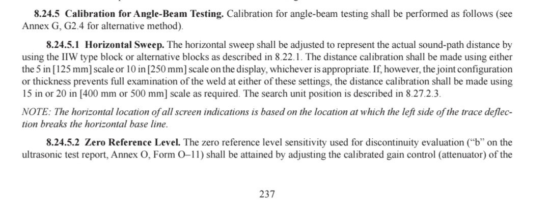
8.24.5 Calibration for Angle-Beam Testing.
Calibration for angle-beam testing shall be performed as follows (see Annex G, G2.4 for alternative method).
8.24.5.1 Horizontal Sweep.
NOTE: The horizontal location of all screen indications is based on the location at which the left side of the trace deflection breaks the horizontal base line."
موقع خوندن عمق (موقعیت افقی) The horizontal location
لبهی چپ سیگنال (آغاز پالس) the left side of the trace deflection
جایی که از خط مبنا جدا میشه breaks the horizontal base line
نه قله یا لبهی راست (بهصورت ضمنی: نه peak و نه right side)

این اپندیکس میگه برای چک کردن اینکه دستگاه (گین یا dB) وقتی دامنه رو کم و زیاد میکنه، دقیق خطی کار میکنه یا نه، نیازی به سه سوراخ FBH نیست! کافیه از همون سوراخ T/2 که خودت گفتی استفاده کنی.
روش اجرا
۱. پروب زاویه ای رو روی بلوک کالیبراسیون بذار (همون شکلی که در Figure I-440 هست).
۲. اکوی SDH با عمق T/2 رو پیدا کن و سیگنال رو ماکزیمایز کن.
۳. حالا حساسیت (گین) رو مطابق جدول زیر تنظیم کن و ببین اون سیگنال داخل محدوده مجاز میافته یا نه:
تنظیم سیگنال مرجع (% ارتفاع صفحه) تغییر dB (کم/زیاد کردن گین) محدوده مجاز سیگنال جدید (% ارتفاع صفحه)
۸۰٪ ۶- دسیبل ۳۵٪ تا ۴۵٪
۸۰٪ ۱۲- دسیبل ۱۵٪ تا ۲۵٪
۴۰٪ ۶+ دسیبل ۶۵٪ تا ۹۵٪
۲۰٪ ۱۲+ دسیبل ۶۵٪ تا ۹۵٪
یعنی چی این اعداد؟
- اول سیگنال رو روی ۸۰٪ تنظیم کن. بعد گین رو ۶ واحد کم کن (۶- dB). اگر دستگاه خطی باشه، سیگنال باید بره پایین بین ۳۵ تا ۴۵ درصد (نه بیشتر، نه کمتر).
- دوباره از ۸۰٪ برو ۱۲ واحد پایینتر، سیگنال باید برسه به ۱۵ تا ۲۵ درصد.
- حالا برو روی ۴۰٪ تنظیم کن، بعد ۶ واحد زیاد کن، باید برسه ۶۵ تا ۹۵٪.
- برو روی ۲۰٪، ۱۲ واحد زیاد کن، بازم باید برسه ۶۵ تا ۹۵٪.
۱۲ دسیبل یعنی یک چهارم ، ۶ دسیبل یعنی یک دوم
-- دقت خواندن: اعداد رو باید با دقت ۱٪ از تمام صفحه بخونی (یعنی با چشم خطکشی کن).
-- تعداد نقاط: برخلاف Appendix III که ۳ نقطه مختلف لازم داشت، اینجا با یک سوراخ T/2 و چهار تغییر dB، خطی بودن کنترل گین رو چک میکنی.
-- زمان انجام: این کار معمولاً همراه با کالیبراسیون روزانه یا وقتی شک داری گین دستگاه درست کار نمیکنه، انجام میشه.
-- فرقش با Appendix III: اون یکی خطی بودن کل سیستم (پروب + دستگاه) رو با سوراخهای مختلف میسنجید، این یکی فقط عملکرد مدار تقویت کننده (گین) دستگاه رو با یک سوراخ ثابت چک میکنه.
انرژی کمتری از نقص به پراب میرسد در نتیجه دامنه کمتری از یک نقص را شاهد هستید و اکوی بک وال همچنان قویتر ( البته در عمق یکسان )

عیب کوچک چیست؟
نقصی که کاملاً درون قطر پرتو صوتی قرار بگیرد، «بازتابکننده کوچک» محسوب میشود.
مشکل اسکن کردن
اگر با روش اسکن (جستجوی دستی) چنین عیبی را بررسی کنید، چیزی که به دست میآورید اندازه واقعی عیب نیست، بلکه قطر پرتو صدا است! بنابراین این روش برای عیوب کوچک کاربردی ندارد.
- راه حل (روش DGS)
میدانیم که هرچه سطح مقطع پرتوی که روی عیب میافتد بیشتر باشد، ارتفاع پژواک (اکو) برگشتی بزرگتر میشود. از همین رفتار برای عیوب کوچک استفاده میشود:
ارتفاع پژواک با افزایش مساحت عیب، افزایش مییابد.
پس به جای اندازهگیری فیزیکی عیب، ارتفاع سیگنال برگشتی را با منحنیهای مرجع DGS مقایسه میکنیم تا اندازه عیب را تخمین بزنیم.
اگر بخواهم خیلی خودمانی بگویم: وقتی عیب از پرتو صدا کوچکتر است، نمیتوانی با حرکت دادن پروب، لبههایش را پیدا کنی. تنها کاری که میشود کرد این است که بلندی پژواک را ببینی و از روی آن، اندازه عیب را حدس بزنی.
Resolution
Resolution is the ability of an equipment/combination probe to distinguish between two echoes from reflectors that are close together. To have good resolution a probe must present two signals on a CRT screen from two separate reflectors: if it has poor resolution the echoes from the two reflectors appear as one signal on the screen.
In the early days of ultrasonic testing we used the 100, 91 and 85mm steps, at the radius end of the V1 block to test resolving power. However, today this is regarded as too crude a test and BS 4331 Part 3 (now obsolete) recommended that we should be able to recognise two discrete echoes less than two wavelengths apart. By discrete echoes they mean split by more than 6dB, or to more than half the total height of the signals.
رزولوشن، توانایی دستگاه و مبدل (Probe) یعنی ترکیبی !!! در تشخیص و تفکیک دو اکو از دو بازتابندهای است که فاصله بسیار کمی از یکدیگر دارند.
برای اینکه یک مبدل رزولوشن خوبی داشته باشد، باید بتواند دو سیگنال مجزا از دو بازتابنده جداگانه را روی صفحه نمایش (CRT) نشان دهد. اگر رزولوشن ضعیف باشد، اکوهای دو بازتابنده به صورت یک سیگنال واحد روی صفحه ظاهر میشوند.
در سالهای اولیه آزمون التراسونیک، از پلههای 100، 91 و 85 میلیمتری در انتهای شعاعی بلوک V1 برای ارزیابی قدرت تفکیک استفاده میشد. اما امروزه این روش آزمون نسبتاً ابتدایی و غیردقیق تلقی میشود.
استاندارد BS 4331 Part 3 (که اکنون منسوخ شده است) توصیه میکرد که دستگاه باید بتواند دو اکوی مجزا را از بازتابندههایی با فاصله کمتر از دو طول موج تشخیص دهد.
منظور از اکوهای مجزا (Discrete Echoes) این است که دو اکو باید بیش از ۶ دسیبل از یکدیگر جدا باشند؛ یعنی افت بین دو قله بیش از ۶ dB باشد، یا به عبارت دیگر، دره بین دو قله به کمتر از نصف ارتفاع کل سیگنالها برسد.

"Approximately 40 percent of the questions on the actual examination are derived from the content of these sample tests."


CRT & Instrumentation Practice
Questions
1. The purpose of the time-base circuit is to:
a) Generate ultrasonic pulses
b) Amplify echoes
c) Move the CRT trace horizontally at a constant rate.
d) Rectify RF signals
2. The received echo signal is applied directly to:
a) X plates
b) Y plates.
c) Pulser
d) Sweep generator
3. In an A-scan display, the horizontal axis represents:
a) Echo amplitude
b) Gain
c) Time or distance.
d) Frequency
4. In an A-scan display, the vertical axis represents:
a) Material thickness
b) Echo amplitude.
c) Velocity
d) Frequency
5. The purpose of the pulser is to generate:
a) Low-voltage dc
b) High-voltage short-duration pulses.
c) RF amplification
d) Time base
6. The sweep voltage is applied to:
a) Receiver amplifier
b) Y plates
c) X plates.
d) Transducer crystal
7. Increasing receiver gain will:
a) Increase pulse voltage
b) Increase echo amplitude on screen.
c) Increase sound velocity
d) Change crystal frequency
8. Which component synchronizes the sweep with the transmitted pulse?
a) Attenuator
b) Trigger circuit.
c) Rectifier
d) Filter
9. A CRT display shows a larger echo height when:
a) Echo amplitude increases.
b) Sound velocity decreases
c) Frequency decreases
d) Sweep speed decreases
10. If the sweep speed is increased:
a) Echoes move farther apart horizontally.
b) Echoes move closer together horizontally
c) Echo height increases
d) Pulse voltage increases
11. The echo signal arriving at the amplifier input is typically:
a) 100–1000 V
b) 50–100 Vc) 1–5 V
d) 0.001–1 V.
12. Which determines the horizontal position of an indication on an A-scan?
a) Gain
b) Echo amplitude
c) Time of flight.
d) Receiver bandwidth
13. What is the role of the pulser in an ultrasonic instrument?
A) Display echoes
B) Generate electrical.
excitation
C) Measure thickness
D) Filter noise
14. The amplifier section primarily functions to:
A) Reduce signal noise only
B) Increase received signal amplitude.
C) Generate pulses
D) Control clock timing
15. The clock system in a UT instrument is used for: A) Probe calibration
B) Time base generation and distance measurement
C) Signal filtering.
D) Couplant control
16. Increasing gain results in:
A) Lower signal height
B) Higher signal height.
C) Changed frequency
D) Reduced penetration
17. Excessive gain may lead to:
A) Loss of all signals
B) Screen saturation and noise.
C) Better resolution
D) Lower sensitivity
18. The pulser output is connected directly to the:
A) Display
B) Transducer.
C) Amplifier
D) Gate.
19. Which component controls timing accuracy?
A) Amplifier
B) Clock.
C) Gate
D) DAC
20. A 6 dB increase in gain approximately:
A) Halves amplitude
B) Doubles amplitude.
C) Triples amplitude
D) No change
21. The main purpose of amplification is to:
A) Modify sound velocity
B) Improve visibility of received echoes.
C) Change probe angle
D) Reduce pulse energy
22. The signal path in UT is:
A) Amplifier → Pulser → Display
B) Pulser → Transducer → Amplifier → Display.
C) Display → Gate → Pulser
D) Clock → Probe → Display
23. Weak echoes are made visible by adjusting:
A) Velocity
B) Gain.
C) Frequency
D) Wedge angle.
24. The clock system is essential for:
A) Color display
B) Distance calibration.
C) Couplant selection
D) Probe wear measurement
25. The pulser primarily controls:
A) Output energy of ultrasonic pulses.
B) Display brightness
C) Material properties
D) Backwall signal only
26. If gain is too low:
A) All signals disappear
B) Only strong reflectors appear.
C) Noise increases
D) Clock fails
27. Amplifier gain affects:
A) Actual flaw size
B) Displayed signal amplitude.
C) Material thickness
D) Sound velocity
28. The time base is synchronized with:
A) Pulser
B) Clock.
C) Couplant
D) Probe wedge
29. High pulser energy generally improves:
A) Penetration.
B) Noise reduction only
C) Display color
D) Clock speed
30. The CRT display shows:
A) Electrical pulses directly
B) Processed ultrasonic signals.
C) Material structure
D) Probe design
31. The X-plates in a CRT are responsible for:
A) Vertical deflection of the electron beam
B) Horizontal deflection of the electron beam.
C) Focusing the electron beam
D) Controlling the brightness
X-plates are mounted vertically on the sides of the tube and create an electric field that deflects the beam left or right.
32 The Y-plates in a CRT are mounted:
A) Vertically (top and bottom).
B) Horizontally (left and right)
C) Behind the cathode
D) Around the fluorescent screen
Y-plates are placed above and below the beam path to deflect it up or down for vertical movement.
33. If the voltage on the left X-plate becomes more positive than the right X-plate, the electron beam deflects:
A) Upward
B) Downward
C) To the left
D) To the right.
Electrons are negatively charged and are attracted toward the positive plate, so beam moves right.
34. Which plates receive the time-base (sweep) voltage in a typical A-scan ultrasound CRT?
A) Y-plates
B) X-plates.
C) Both equally
D) Neither, it goes to the grid
The sweep generator applies a ramp voltage to the X-plates to move the spot horizontally across the screen with time.
35. The amplified echo signal is applied to which plates in an A-scan display?
A) X-plates
B) Y-plates.
C) Filament
D) Anode
The echo amplitude (voltage) is fed to Y-plates to move the beam vertically, creating the vertical pulse height.
36. If both X-plates and Y-plates receive zero voltage difference, the electron beam strikes:
A) Bottom-left corner
B) Top-right corner
C) Center of the screen.
D) Nowhere (turns off)
With no deflection voltage, the beam passes straight through and hits the center.
37. In the immersion technique, the water path is usually adjusted so that the time for the sound to travel through the water is:
A) Equal to the time in the test piece
B) Greater than the time in the test piece
C) Less than the time in the test piece.
D) Dependent only on water temperature
This prevents the multiple echoes from the water path from overlapping with the back-wall echoes of the test piece, avoiding confusion in interpretation.
38. When examining materials for planar flaws oriented parallel to the part surface, which testing method is most often used?
A) Angle beam
B) Through-transmission
C) Straight beam.
D) Dual crystal
Straight beam (longitudinal wave) is most effective for detecting laminar-type discontinuities that are parallel to the test surface.
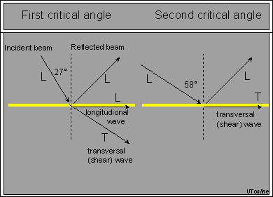
39. The first critical angle is defined as the longitudinal wave incident angle which results in:
A) A 90° refracted shear wave
B) A 90° refracted longitudinal wave.
C) A surface wave
D) Total reflection of the longitudinal wave
At the first critical angle, the refracted longitudinal wave propagates along the interface at 90°. Increasing the angle beyond this eliminates the longitudinal wave in the second material.
40. If a contact angle beam transducer produces a 45° shear wave in steel (Vs=0.323 cm/µs), what angle would the same transducer produce in aluminum (Vs=0.310 cm/µs)?
A) Greater than 45°
B) Less than 45.
C) Exactly 45°
D) Unknown, more information is required
Using Snell's Law, if the sound velocity in the second material (aluminum) is lower, the refracted angle will also be smaller.
41. In an A-scan display, the "dead zone" refers to:
A) The distance contained within the near field
B) The area outside the beam spread
C) The distance covered by the front surface pulse width and recovery time.
D) The area between the near field and the far field
The dead zone is the initial period after the initial pulse where the instrument is recovering and cannot detect echoes, masking defects near the surface.
42. Acoustic energy propagates in different modes. Which of the following represents a mode?
A) High-frequency ultrasonic waves
B) A shear wav
C) The dissipation factor
D) The wave movement in the direction from the point where the energy was introduced
Wave modes refer to the type of particle motion, such as Longitudinal (compression), Shear (transverse), Surface (Rayleigh), or Lamb waves.
43. When using focused transducers, nonsymmetry in a propagated sound beam may be caused by:
A) Backing material variations.
B) Mode conversion
C) Diffraction characteristics
D) Irregular sound beam exit point
Variations in the backing material can cause uneven damping or vibrations, leading to a non-uniform or asymmetric sound beam.
44. A decrease in echo amplitude from the back-wall of a test piece could be caused by:
A) An increase in material density
B) A decrease in material attenuation
C) A reflector or discontinuity in the sound path.
D) An increase in transducer frequency
Any reflector between the transducer and the back-wall will scatter or reflect part of the sound energy, reducing the energy reaching the back-wall and thus lowering its echo amplitude.
45. The loss of sound energy due to scattering and absorption in a material is called:
A) Refraction
B) Attenuation.
C) Divergence
D) Mode conversion
Attenuation includes both absorption (conversion to heat) and scattering (redirection of sound by grain boundaries or inclusions), which together reduce sound intensity with distance.
46. Which of the following would cause the highest attenuation in a material?
A) Fine equiaxed grain structure
B) Coarse grain structure.
C) Single crystal structure
D) Low carbon steel
Coarse grains cause more scattering of the ultrasonic beam, leading to higher attenuation, reduced signal-to-noise ratio, and lower penetration.
47. A "skip" in angle beam inspection is defined as:
A) One complete V-path from transducer to back-wall and back.
B) One half of a V-path
C) The distance from the transducer to the first reflector
D) The time between two consecutive echoes
One skip is the sound path from the transducer to the back-wall, reflecting and returning to the scanning surface at another point, forming a "V" shape.
48. In angle beam testing, the echo from a side-drilled hole (SDH) appears on the screen. If you move the transducer toward the hole while maintaining the same refracted angle, what happens to the echo amplitude?
A) It continuously increases
B) It continuously decreases
C) It increases to a maximum and then decreases.
D) It remains constant
As the transducer moves, the beam intersects the hole at different points. Maximum echo occurs when the beam axis hits the center of the hole (maximum reflector cross-section); moving further causes a drop-off.
49. A sudden drop in the back-wall echo amplitude with no visible defect indication might be due to:
A) A change in material thickness
B) A change in couplant thickness
C) A laminar discontinuity parallel to the surface
D) All of the above.
All three can reduce back-wall echo: thinner section changes propagation, couplant variation affects energy transfer, and laminations block or scatter the beam before reaching the back-wall.
50. The effect of increasing transducer frequency on attenuation in a given material is that attenuation will:
A) Decrease
B) Increase.
C) Remain the same
D) Be unaffected
Higher frequency results in more scattering per unit distance (especially in coarse-grained materials), so attenuation increases. That's why lower frequencies are used for coarse-grained materials.
.
51. The wave mode that has multiple or varying wave velocities is:
a. longitudinal waves
b. shear waves
c. transverse waves
d. lamb waves.
52. Which of the following would be considered application(s) of ultrasonic techniques?
a. Determination of a material's coefficient of expansion
b. Study of a material's metallurgical structure.
c. Determination of a material's chemical composition
d. Evaluation of surface tension through capillary action
53. The only significant sound wave mode that travels through a liquid is:
a. shear wave
b. longitudinal wave.
c. surface wave
d. rayleigh wave
54. The acoustic impedance of a material is used to determine the:
a. angle of refraction at an interface
b. attenuation within the material
c. relative amounts of sound energy coupled through and reflected at an interface.
d. beam spread within the material
55. When angle beam contact testing a test piece, increasing the incident angle until the second critical angle is reached may result in:
a. total reflection of a surface wave
b. 45° refraction of the shear wave
c. production of a surface wave.
d. a 90° angle of refraction for the wave
56. Acoustic energy propagates in different modes. Which of the following represents a mode?
a. High-frequency ultrasonic waves
b. A shear wave.
c. The dissipation factor
d. The wave movement in the direction from the point where the energy was introduced
57. The simple experiment where a stick in a glass of water appears disjointed at the water surface illustrates the phenomenon of:
a. reflection
b. magnification
c. refraction.
d. diffraction
58. The crystal thickness and transducer frequency are related. The thinner the crystal:
a. the lower the frequency
b. the higher the frequency.
c. there is no appreciable effect
d. the lower the attenuation
BEAM SPREAD OR DIVERGENCE واگرایی پرتو
Question 1:
The sound beam intensity at the acoustic axis is considered as the reference (0 dB). At what point in the far field does the sound pressure drop to half of its maximum value?
A) At the near field boundary
B) At the beam spread angle where the intensity is 20 dB down
C) At the half‑power points (beam edges) where the intensity is 6 dB down.
D) At the focus point of the transducer
توضیح مفهومی: در لبههای پرتو (نیمتوان)، شدت به نصف (۵۰٪) میرسد که معادل افت ۶ دسیبل است. این نقاط، مرز مؤثر پرتو برای تشخیص عیوب هستند.
Question 2:
A flat-bottom hole (FBH) is scanned in the far field of a transducer. The echo amplitude is maximum when the reflector is exactly on the beam centerline. If the same reflector is moved laterally to the 6‑dB beam edge, what will be the ratio of the new echo amplitude to the maximum amplitude?
A) 10:1
B) 2:1
C) 1:2
D) 1:10
توضیح مفهومی: در لبه ۶ دسیبل، شدت نصف مرکز میشود، بنابراین نسبت دامنه جدید به دامنه ماکزیمم برابر ۱ به ۲ (یا به عبارت دیگر نسبت دامنه ماکزیمم به جدید برابر ۲ به ۱) است.
Question 3:
In the far field of a transducer, the sound pressure at the outer limits of the beam (the maximum divergence angle) is approximately:
A) 6 dB down from the centerline
B) 20 dB down from the centerline .
C) 3 dB down from the centerline
D) Equal to the centerline intensity
توضیح مفهومی: در حداکثر زاویه واگرایی (لبه فیزیکی پرتو)، شدت به حدود ۱۰٪ (یکدهم) مقدار مرکز میرسد که معادل افت ۲۰ دسیبل است. این مرز، انتهای ناحیهای است که موج به آنجا میرسد.
نکته طلایی برای آزمون: اگر سوال پرسید "مرز مؤثر پرتو برای تشخیص عیب کدام است؟" پاسخ ۶- دسیبل است. اگر پرسید "مرز فیزیکی یا حداکثر واگرایی کدام است؟" پاسخ ۲۰- دسیبل است. این دو عدد را حتماً از هم تفکیک کنید.

ارزیابی ارتفاع ترک بر اساس اندازهگیری نسبی مسیر فراصوت بین سیگنالهای نوک ترک و تله گوشه ترک


تکنیک کاهش 6 دسیبل Gain


اکوی بلند ، تک ، باریک در محور افقی دستگاه یا time base و اکوی ضعیف در اسکن از سمت دیگر.
در اسکن چرخشی یا دورانی اکو به شدت افت میکند ولی در حرکت پراب به حالت جانبی یا به موازات خط جوش ارتفاع اکو تغییر زیادی ندارد.
برای اندازه عمق از تکنیک کاهش 6 دسیبل یا 20 دسیبل و طول از تکنیک کاهش 6 دسیبل استفاده می شود.

A common procedure is the “6 dB drop technique”, demonstrated in the graphic below, in which the probe is moved from left to right while noting the two points where the maximum reflection that is seen at the middle of the flaw drops to 50% at the edges. The distance between the probe center at each of those two points represents the width of the flaw. Other procedures may use a different amplitude point as the reference.

تکنیک نیم دامنه / افت ۶ دسیبل: تکنیک نیم دامنه برای تعیین انتهای یک ناپیوستگی زمانی استفاده میشود که طول آن از اندازه کریستال پروب بیشتر باشد. این تکنیک محبوبترین تکنیک برای اندازهگیری طول ناپیوستگی است. پس از به حداکثر رساندن نشانگر ناپیوستگی، این سیگنال را روی ارتفاع مناسب [~ ۸۰٪] تنظیم کنید. سپس پروب به سمت راست، موازی با ناپیوستگی یا درز جوش، به صورت مناسب، تا موقعیتی که سیگنال به نصف دامنه تنظیم شده کاهش مییابد، حرکت داده میشود. نقطهای با یک نشانگر بالای محل ناپیوستگی مربوط به خط مرکزی کریستال پروب علامتگذاری میشود. با حرکت دادن پروب به سمت چپ، نقطه مشابهی پیدا میشود. فاصله بین این دو نقطه، طول ناپیوستگی است. طول ناپیوستگی اندازهگیری شده با این تکنیک همیشه منجر به تخمین بیش از حد اندازه واقعی میشود. این به این دلیل است که خط نیم شدت در زاویهای نسبت به محور اصلی پرتو [خط مرکزی کریستال] قرار دارد.
تصاویر زیر برای اندازه گیری طول عیوبی مثل عدم ذوب یا ترک طولی از تکنیک کاهش 6 دسیبل Gain استفاده کرده ( البته کالیبره حساسیت رو بکار نبرده ) . کالیبره مسافت با استفاده از بلوک iiw و انحنای ۴ اینچی و ۱ اینچی انجام شده که دو اکو دریافت شده و Sound path یکی بر روی ۴ اینچ با دستکاری Probe Delay و دیگری بر روی ۱۰ اینچ با دستکاری MTLVEL تنظیم شده ( قبل از کالیبره حتما rejection خاموش یا صفر باشد و همینطور Probe delay و Material velocity یا MTLVEL ) . نحوه کالیبره به این صورت انجام شده که بدون اینکه Gate را روی اکوها ببرد ماکزیمم اکو از شعاع ۴ اینچی را گرفته ( با عقب و جلوکردن پراب ) و با دستکاری Probe Delay پای اکو را به عدد ۴ روی محور افقی صفحه رسانده و سپس gain را افزایش داده تا اکوی دوم هم در صفحه بالا بیاد ( بالاترین اکو ) دوباره پراب را کمی حرکت داده تا ماکزیمم را بگیرد و با دستکاری MTLVEL اکوی دوم را به حدود ۹ اینچ محور افقی رسانده ... Gate را روی اکوی اول برده پراب را کمی حرکت داده تا به ۴ اینچ برسد سپس Gate را به اکوی دوم برده که همان ۹ اینچ را تقریبا نمایش داده .
در این حالت عدد gain روی 59 است 6dB به gain افزوده ( 65dB ) و شروع به جستجو برای ناپیوستگی کرده. یک سیگنال شارپی دریافت کرده سپس دوباره 6dB کاهش gain داده در همین ارتفاع ماکزیمم پراب را به سمت چپ حرکت داده تا ارتفاع اکو به نصف برسد از وسط پراب خطی روی جوش ترسیم نموده دوباره پراب را به سمت مخالف حرکت داده اول اکو ماکزیمم میشود سپس دوباره به نصف تقلیل می یابد در همین حال از وسط پراب دوباره خطی عمود بر روی جوش می کشیم دو نقطه را بهم متصل می کنیم که طول عیب است.


Range :
در تست با پروب های زاویه ای آگاهی از زاویه دقیق پروب، نقطه ایندکس پروب و طول مسیر صوت تا یک نقطه منعکس کننده استاندارد ( sound path ) اهمیت خاصی دارد این کمیت ها بصورت زیر می باشد.
اگر زاویه واقعی پروب برابر زاویه اسمی آن باشد یعنی مثال پروب 60 درجه شما دقیقا ( بدون خطا ) در زاویه60 درجه باشد،دراین حالت فواصل مذبور را می توان از رابطه زیر به سادگی بدست آورد: که برای بدست آوردن محدوده کاری ضروری می باشند.
اگر می خواهیم ریشه قطعه کاری با ضخامت 20 میلیمتری را با پروب زاویه ای تست کنیم در ابتدا باید محدوده کاری تا ریشه را طبق فرمول زیر بدست آورد:
Sound path=t/Cosθ که مسیر صوت با توجه به مشخصات فوق برای ریشه برابر است با 40 میلیمتر به این منظور که اگر بدنبال عیوب در ریشه جوش هستیم باید محدوده تست بیشتر از 40 میلیمتر باشد تا بتوان عیوب مربوط به ریشه را در صفحه دستگاه مشاهده کرد.حال اگر بدنبال عیوب نزدیک به سطح یا عیوب های سطحی هستیم باید از فرمول زیر برای تعیین محدوده تست استفاده کرد.
Sound path=2t/Cosθ که مسیر صوت باتوجه به مشخصات فوق برای روئیت عیوب های سطحی برابر است با 80 میلیمتر که می بایست برای مشاهده عیوب های سطحی محدوده تست را بیشتر از یک جهش کامل قرار داد.
در حالت سوم بهتر است که range یا محدوده دستگاه را در هنگام ابتدای تست از لحاظ تجربی برای پروب زاویه ای برابر فرمول زیر قرار داد.
1.2×(Range=(2t/Cosθ در این فرمول میتوان تمام قسمت قطعه کار را تست کرد اما اگر عیبی یافت شود که عمق آن برابر یا بیشتر از 1.5 برابر اینچ باشد بهتر است که از روش delay برای تعیین دقیق عمق عیب استفاده کرد همانطورکه دراستاندارد AWS D1.1 ANNEX S نیز بیان شده است.
S6.3 Shear Wave
86.3.1 Depth (Horizontal Sweep). Indications from the selected standard reflectors should be used to cover the maximum depth to be used during examination in conformance with Figure S.7. Accuracy should be within ± 1% to facilitate the most accurate discontinuity height measurement. The delay technique should be used for discontinuities with depth greater than approximately 1.5 in to maximize the most accurate discontinuity depth reading (and discontinuity height) accuracy

کالیبره مسافت انجام شده ... کلیدهای میانبر روی صفحه برای دسترسی به صفحات یا کم و زیاد کردن دسیبل یا حرکت دادن gate و ... تعبیه شده.
مثلا برای گرفتن ماکزیمم پیک با دقت خوب می توانید دکمه Gate را بزنید ، با چرخش دکمه گردان مشکی سمت راست آنرا روی پیک مورد نظر برده کلید Zoom را فشار دهید تا تنها آن پیک در تمام صفحه برای شما نمایش داده شود سپس دکمه Envelope کنار Zoom را زده ، با اینکار و حرکت پراب یک منحنی نامنظمی تشکیل میشود هر جا که پیک در منحنی بالاترین بود دکمه Envelope و zoom را زده تا به صفحه اصلی برگردید.

از Side drill hole بلوک V1 از قطر 1.5 میلیمتر پیک ماکزیمم را دریافت میکنیم .

قبل از رفتن به منوی AWS با Next Page به منوی Gain میرویم و Auto Gain را روی 40 تا 60 درصد تنظیم می کنیم که اینجا روی 50 درصد قرار داده شده... زمانیکه دکمه میانبر Auto یا Auto gain روی صفحه را می زنیم سیگنال که gate رو آن است به 50 درصد صفحه یا FSH میرسد.

با چند بار فشردن دکمه Next page به منوی AWS میرویم Reference را فعال می کنیم دکمه Auto Gain رو فشار می دهیم تا ارتفاع پیک دریافتی از Side drill hole را به 50 درصد برساند. در بالای صفحه نمایش سمت چپ نمایش داده شده H50.2%

با چرخاندن ولوم مشکی gain مرجع اتومات درج میگردد 44.9+


می توانیم با استفاده از بلوک V2 با سوراخ 1.5 میلیمتر ، پیکی دریافت کنیم ... gate را روی پیک برده و روی گزینه INDICA که همان gain عیب است میرویم سپس دکمه Auto gain را فشار می دهیم تا به 50 درصد ارتفاع صفحه یا FSH برسد

طبق تصویر بالا نرخ عیب یا D RATING و فاکتور تضعیف یا Attenuation factor بطور اتومات نمایش داده شده. هر چقدر این مقدار به سمت پائین و منفی سوق پیدا کند عیب بزرگ است و در کلاس A که صرفنظر از طول رد است قرار میگیرد.

البته طبق استاندارد AWS چون شرایط تست بلوک و قطعه مورد آزمون از نظر دانه بندی و غیره یکسان نیست طبق عدد sound path عیب مرجع یا Reference باید به Reference مقداری اضافه شود مثلا سرعت تا 65 میلیمتر 19 واحد به Gain مرجع یا Reference باید اضافه کنیم بعلت تضعیف صوت و اینکه ما با سوراخ 1.5 میلیمتر بلوک V1 که عمق کمی دارد gain را گرفتیم ولی ممکن است عیب در قطعه تست در عمق بیشتری باشد.
پیک لبه

6db drop
با حرکت دادن پراب روی قطعه تست یک نشانه شارپ دریافت شد. برای سایزینگ یکبار ( اسکن لترال ) به سمت راست ( gif اول ) حرکت داده می شود تا سیگنال به نصف ارتفاع برسد سپس از وسط پراب روی جوش علامت میزنیم دوباره به سمت چپ حرکت می کنیم سیگنال ماکزیمم میشود زمانی که دوباره به نصف ارتفاع رسید مجدد از وسط پراب روی جوش علامت میزنیم خط بین این دو علامت طول عیب خواهد بود.


کالیبراسیون مسافت یا محور افقی :
-Rejection خاموش باشد.
-اول Probe Delay را صفر می کنیم.
-Angle را برای پراب زاویه ای انتخاب می کنیم و MTLVEL را روی 3230 یا 3240 تنظیم میکنیم
- Sound path اولین اکو را با Probe-Delay و آخری را با MTVEL یا Material velocity تنظیم می کنیم و با Gate روی اکو ها میرویم و ممکن است اینکار را چندین بار انجام دهیم تا مسیرصوت درست را نمایش دهد البته در بعضی دستگاه های دیجیتال با دادن عدد مسیر صوت اول و دوم بعنوان s1 و s2 و record کردن آنها با توجه به رنجی که حداقل دو اکو دریافت کنیم Probe delay و MTLVEL را خودش تنظیم میکند.
رزولوشن :
میزان تفکیک چند ناپیوستگی کنارهم ، تصویر دوم را ملاحظه کنید.

کالیبراسیون حساسیت یا Sensivity برای پراب زاویه ای :
-تنظیم دسیبل بل دستگاه با توجه به اکوی برگشتی از انعکاس دهنده های مرجع که بسته به استاندارد می تواند سوراخ کناری 1.5 میلیمتری Block iiw باشد یا Notch در استاندارد ASME برای لوله های 20 اینچ و پائین تر که قطر این سوراخ ها بسته به ضخامت تغییر می کند.
-قدرت تفکیک چند ناپیوستگی در کنارهم ( پراب نرمال )

بلوک DAC صفحه ای دارای سه سوراخ به عمق 1/4t ، 2/4t ، 3/4t است و بلوک Curve دارای شیار بیرونی و داخلی است
برای ترسیم Reference level در DAC ، اکوی LEG1 هر سوراخ به ترتیب از کمترین تا بیشترین عمق زده شده و رکورد میشود ( اکوی اول به ارتفاع 80 درصد برسد و بقیه سوراخ ها اکوی ماکزیمم )حداقل سه سوراخ نیاز است با عمق گرفتن سوراخ ها و بیشتر شدن مسیر صوت ارتفاع اکو ها کمتر میشود برای دقیقتر شدن با نقاط بیشتر از 3 تا بصورت برعکس عمل می کنیم یعنی اول Leg2 سوراخ 3/4 سپس 1/2 و ششمی سوراخ 1/4.
معمولا سمت چپ اکوی مورد نظر است چون اکویی از دسته پرتو به سوراخ میخورد و اکویی دیگر به کنار دیواره و چون مسیر بیشتری طی میکند با جابجایی پراب طبیعتا با افت اکو همراه خواهد بود و اکوی سوراخ وقتی مسیر صوت به آن عمود میشود شارپ تر و مرتفع تر است.


در شکل زیر از بلوک DAC استفاده شده ماکزیمم اکو از leg1 سوراخ 1/4t را گرفته و با تغییر Gain ارتفاع را به 80 درصد صفحه رسانده و بعد فشردن Enter ( در این دستگاه کلیدهای سمت راست وظیفه تغییر یا کم و زیاد کردن را دارند ... فلش قرمز رنگ را ملاحظه کنید ) ... اکوی leg2 سوراخ 2/4t یا 1/2t را گرفته و بعد Enter را زده و gain را به همان 55 دسیبل بل سوراخ 1/4 تغییر داده ( دسیبل هر سه تصویر را ببینید ) در انتها اکوی Leg3 سوراخ 3/4t را گرفته Enter را زده و سپس gain را به 55 دسیبل رسانده ... برای گرفتن نقاط یا point بیشتر ، از سوراخ 3/4 به 1/4 چون بصورت curve باید باشد


LOP : عدم نفوذ
- در ریشه جوش اتفاق می افتد.
- در Leg1 اکوی بلندی و شارپی دارد در Leg2 دریافت نمی شود.
- برای صحت باید از هر دو طرف اکو گرفته شود.
- حتما index probe در خط Hsd کشیده شده باشد ( Hsd از مرکز جوش با فرمول ضخامت در تانژانت زاویه دقیقا پراب بدست می آید ).

Excess penteration : نفوذ اضافی ریشه
- در پاس ریشه است.
- اکوی بلند و شارپی دریافت میشود.
- در انتهای Leg1 و ابتدای Leg2.
- تقریبا چند میلیمتر وارد Leg2 شده.
- تمایزش با عیب LOP دشوار است.
- برای تمایز ایندکس پراب را دقیقا روی HSD قرار داده مقداری از آن را در ابتدای Leg2 دریافت می کنیم و پای چپ اکو در Leg1 قرار دارد. دستگاه مسیر اضافه صوت را که از ریشه فراتر زده بعنوان Leg2 دریافت نظر میگیرد به این علت مقداری از اکو در ابتدای Leg2 دریافت میشود.
- Excess یک عیب حجمی است که با حرکت اسکن به اشکال مختلف می توان حجمی بودن آنرا تشخیص داد.
- با اسکن Rotational در حد 10 درجه عیب Excess افت کمی دارد و همچنان اکو را داریم ( کوتاه نه بلند ) ولی در LOP اکو به سرعت افت می کند.

افت سریع اکو با اسکن Rotational

Root LOF : عدم ذوب در ریشه :
در یکطرف در Leg1 قابل دریافت نیست چون دسته پرتو عمود بر ناپیوستگی است و بازتابی به پراب برنمی گردد که در Leg2 باید دریافت کرد و در یکطرف پرتو در Leg1 عمود بر ناپیوستگی است.

(LOF (SLAG :
LOF بدلیل چسبیدن Slag در ریشه اتفاق بیوفته
- از یکطرف در Leg1 چون دسته پرتو عمود بر Slag است قابل دریافت است و اکو ها چند وجهی است ( multifaced ) یا دندانه ای ... از یکطرف در leg1 قابل دریافت نیست چون پرتو به صفحه عمود نیست ولی در Leg2 بصورت اکوی بلند و شارپ دریافت می شود ( Planner یا صفحه ای است ).
Side Wall Lof : زمانیکه در دیواره اتفاق بیوفتد
از یک سمت در Leg1 قابل دریافت است و از سمت دیگر در Leg2 قابل دریافت است ... زمانیکه عیب در میانه جوش است اگر در نیمه بالایی باشد در Leg1 قابل دریافت نیست.

Slag inclusion :
- بستگی به موقعیتش در جوش در Leg1 یا Leg2 می توان پیک را دریافت کرد.
- عیب حجمی است و با اسکن Rotational قابل تشخیص است بخاطر شکل هندسی نامنظم معمولا پیک ها بصورت دندانه دار است و تغییر می کند.


Cluster porosity :
- اگر تخلخل ریز باشد اکو ها چمنی است.
- با اسکن Orbital اکو ها باقی میماند و افتی ندارند.
- چون عیب حجمی است با جابجایی کم پراب اکو ها تغییر شکل و ارتفاع می دهند و با اسکن Rotaional و Orbital از هر دو سمت قابل دریافت است.

Root concavity :
- در پاس ریشه است.
- تمایزش با Excess این است که اگر ایندکس پراب را در قسمت HSD قرار دهیم Excess تقریبا اندکی در ابتدای Leg2 دریافت میشود ولی Concavity در Leg1.
Logintudinal Crack یا ترک طولی :
- شکل اکو بصورت multipeak یا دندانه دار است.
- با انواع اسکن غیرخطی بودن آن را می شود تشخیص داد.
Crack Reverse یا ترک برعکس یا عمود بر جوش
- با اسکن Orbital یا Rotational میشود تشخیص داد که عیب حجمی نیست چون به شدت افت می کند.
- باجابجایی پراب به چپ و راست متوجه میشویم که عیب چندصفحه ایران است و شاهد افت قسمتی از اکو و بلندشدن قسمت دیگر می شویم.
- اگر در ریشه باشد با توجه به عمق می فهیم در ریشه است.
Burn Through یا سوختگی پاس ریشه بعلت آمپر زیاد ، دهانه ریشه بیش از اندازه یا استفاده از الکترود با قطر نامناسب
- در انتهای Leg1 دریافت میشود و مثل Slag شک نامنظم دارد حالت دندانه دار .
- در اسکن Lateral سریع افت میکند.
Hi-Low یا عدم هم ترازی
- عیب حجمی
- با قرار گیری ایندکس پراب در HSD اکو از یکطرف مثل LOP قابل دریافت است و از طرف دیگر اکویی دریافت نمیشود.
- باید چک کرد که در کل خط جوش از یکطرف اکو را داشته باشیم تا بتوانیم قضاوت کنیم
Excess weld reinforcement یا گرده بیش از اندازه
- وقتی گرده بیش از اندازه باشد صوت از Leg2 خارج میشود و این مسیر اضافه بعنوان Leg3 در نظر گرفته میشود که اکویی در Leg3 دریافت می کنیم


6Db OR 20Db DROP


نوع عیب :
- LOP یا عدم نفوذ ( در دسته غیر حجمی یا NON VOLUMETERIC ) :
در جوش Single V پیک بالایی از هر دو طرف ورق جوش شده دریافت می شود و به سرعت در اسکن چرخشی یا Rotational افت می کند در Half skip قابل دریافت است .
- LOF یا عدم ذوب ( در دسته غیر حجمی یا NON VOLUMETERIC ) :
پیک بلندی دریافت می شود ، در اسکن دورانی یا چرخشی به سرعت افت می کند و پیک در اسکن lateral یا افقی ( حرکت پراب در راستای جوش ) باقی می ماند بین Half skip و Full skip دریافت می شود.
- Crack یا ترک ( در دسته غیر حجمی یا NON VOLUMETERIC ) :
ترک می تواند در پنجه یا منطقه متاثر از حرارت ، مرکز جوش و ریشه باشد ، بازتابنده با دامنه بالا و چند وجهی بین Half skip و Full skip . افزایش و کاهش سیگنال روی چرخش و اسکن جانبی . کاهش دامنه در اسکن دورانی

اسلام هیچگاه شکست نخورده

در مورد ترکها، معمولاً وجوه ترکها همراه با سیگنال انکسار یافته از نوک قابل مشاهده هستند و هنگامی که پروب کج ( Skewed) میشود، سیگنال در مقایسه با سیگنال عدم جوش خوردگی ریشه ( LOF ) ، طولانیتر باقی میماند. سیگنال بازتابنده همچنین دارای پایه پهنتری نسبت به عدم جوش خوردگی ریشه خواهد بود. ویژگیهای عدم جوش خوردگی ریشه ( LOF ) مشابه عدم جوش خوردگی دیواره جانبی ( Sidewall fusion ) خواهد بود، اما میتواند ناهموارتر و کمی بیشتر باشد.
مشخصات سیگنال LOP : سیگنال مربوط به عدم نفوذ ریشه معمولاً دارای پایه پهن و دامنه ( Amplitude ) بالایی است. سیگنال آن معمولاً هنگام کج شدن پروب برای مدت کوتاهی ادامه مییابد.

24 خرداد 1404 درپی حمله صبح جمعه اسرائیل به ایران و حذف چندین تن از سرداران سپاه و دانشمندان هسته ای توسط عوامل نفوذی و غفلت اطلاعات ایران:
باشگاه خبرنگاران جوان - سازمان اطلاعات سپاه هشدار داد که هرگونه همکاری با موساد اشد مجازات را در پیدارد.
در این اطلاعیه آمده است: برابر مادههای ۶، ٧، ٨ و ١٠ قانون مقابله با اقدامات خصمانه رژیم صهیونیستی، هرگونه همکاری اطلاعاتی با موساد، تعامل یا تبادل اطلاعات با افراد رسمی و غیررسمی رژیم صهیونیستی و هرگونه اقدام فرهنگی، رسانهای، تبلیغی و مساعدت در جهت تأیید یا تقویت و تحکیم رژیم صهیونیستی، جرم بوده و مرتکب به اشد مجازات قانونی محکوم خواهد شد.

بر اثر این انفجار بخشی از پالایشگاه فجر جم فاز ۱۴ پارس جنوبی دچار آتشسوزی شده است
هنوز از میزان خسارت احتمالی این انفجاز خبری در دست نیست.
نیروهای پدافند و امدادی با موفقیت در حال مدیریت اوضاع هستند و جای نگرانی نیست.

به گزارش خبرآنلاین، تقریباً تمام موشکهایی که ایران در این موج شلیک کرد، مدلهای ۲۰ تا ۳۰ سال پیش بودند، اما به تک موشک نسل جدیدتری که به حیفا برخورد کرد نگاه کنید. بعد ببینید برق قطع میشود. صبر کنید تا ایران ذخایر قدیمی خود را خالی کند،آن وقت اوضاع برای این رژیم نسلکش جالبتر خواهد شد.


26 خرداد 1404 ساعت 17:30

14 دقیقه قبل از اصابت به صداوسیما اعلام کرده بودند سحر امامی ساعت 18:35 در حال خواندن اعلامیه نسبت به مجازات جاسوسان ستون پنجم بود که انفجاری رخ داد.


سه شنبه 27 خردادماه 1404
ترامپ در پیام خود تأکید کرد: «ایران باید توافقی را که به آنها گفتم، امضا میکرد. چه تأسفبار و چه اتلاف جان انسانها. بهصراحت اعلام میکنم ایران نباید به سلاح هستهای دست پیدا کند. بارها این را گفتهام! همه باید فوراً تهران را تخلیه کنند!»


یکشنبه 1404/04/01
«دونالد ترامپ» رئیسجمهور آمریکا روز یکشنبه و پس از سخنرانی خود در پی اقدام تجاوزکارانه در حمله به تاسیسات هستهای ایران، از ایران خواست که به این اقدام پاسخ ندهد!
ترامپ در پیامی که نشان از وحشت او از اقدام تلافیجویانه ایران دارد، نوشت: هر اقدام تلافیجویانه از جانب ایران علیه ایالات متحده آمریکا با نیرویی بسیار بیشتر آنچه امشب دیدید، پاسخ داده خواهد شد».
ایران پیش از این تهدید کرده بود به هر اقدام تجاوزکارانه آمریکا، پاسخ قاطع میدهد
به گزارش خبرآنلاین، به نقل از پایگاه خبری النشره، ولادیمیر پوتین رئیس جمهور روسیه از اینکه دنیا به سمت جنگ جهانی سوم پیش میرود، ابراز نگرانی کرد.
وی در گفتگو با خبرنگاران در این خصوص ابراز داشت: اوضاع نگران کننده است، من بدون شوخی یا تمسخر این را میگویم، احتمال زیادی برای وقوع این جنگ وجود دارد و این احتمال در حال افزایش است و این روند که در برابر دیدگان ما دنبال میشود، تأثیرات مستقیمی بر ما خواهد داشت.
رئیس ستاد مشترک ارتش آمریکا روز یکشنبه در اظهاراتی اعلام کرد که در عملیاتی تحت عنوان «چکش نیمهشب» علاوه بر موشکهای تاماهاک، با ۱۴ بمب سنگرشکن (MOP) به تأسیسات هستهای ایران حمله کردهاند.
به گزارش فارس؛ بنا بر گزارش دن کین، رئیس ستاد مشترک ارتش آمریکا، این کشور در حملات خود به سایتهای هستهای در ایران از ۱۲۵ هواپیمای جنگی استفاده کرده است.

دبیرکل ناتو با حمایت از تجاوزگری آمریکا به حاکمیت ملی و تمامیت ارضی ایران باز هم ادعای وجود اهداف نظامی در برنامه هستهای ایران را تکرار کرده و گفت که همپیمانان این ائتلاف نظامی غربی موافق دست نیافتن ایران به سلاحی اتمی هستند.
2 تیر 1404
رسانه آمریکایی فاکسنیوز اعلام کرد: حمله قریبالوقوع ایران به پایگاه آمریکا در قطر در راه است.
شبکه فاکسنیوز آمریکا به نقل از «منابع آگاه» مدعی شد که حمله قریبالوقوع ایران علیه پایگاه هوایی «العدید» آمریکا در قطر در راه است.
ساعاتی پیش وزارت خارجه قطر با انتشار بیانیهای اعلام کرد که این کشور تا اطلاع ثانوی حریم هواییاش را بسته است.
رسانههای اماراتی نیز از آغاز بسته شدن حریم هوایی این کشور خبر دادند.
-حمله ایران به پایگاه های آمریکا در منطقه آغاز شد. صدای آژیر در پایگاه های آمریکا در سراسر منطقه به صدا درآمده است.
منابع خبری از انفجارهای شدید قطر و عراق خبر داده اند.
اکسیوس مدعی شد که ایران شش موشک به سمت پایگاه آمریکا در عراق پرتاب کرد. گفته شده که شلیک موشک همچنان ادامه دارد.
پایگاه العدید قطر را هدف تهاجم ویرانگر و قدرتمند موشکی قرار داده است. این پایگاه، مقر سرفرماندهی نیروی هوایی و بزرگترین دارایی راهبردی ارتش تروریستی آمریکا در منطقه غرب آسیا است.

ساعاتی پس از این عملیات موفقیتآمیز، شبکه آمریکایی «سی ان ان» به نقل از یک مقام ارشد کاخ سفید نوشت: «دولت ترامپ در انتظار واکنش تلافیجویانه ایران بود. ترامپ به حمله ایران پاسخ نخواهد داد. او بهدنبال درگیری بیشتر نظامی در منطقه نیست.»

1404/04/03
آتش بس ایران و اسرائیل شرط نقض آتش بس ادامه تجاوز از ساعت 4 صبح ببعد بود
متن کامل رئیسجمهور آمریکا به شرح ذیل است: این آتشبس از حدود ۶ ساعت دیگر، پس از آنکه دو طرف مأموریتهای نهایی خود را به پایان رساندند، آغاز خواهد شد. این آتشبس به مدت ۱۲ ساعت ادامه خواهد داشت و پس از آن، جنگ به طور رسمی پایانیافته تلقی میشود.
طبق توافق، ایران آغازگر آتشبس خواهد بود و پس از ۱۲ ساعت، اسرائیل آتشبس خود را آغاز میکند. با رسیدن به ساعت ۲۴، پایان رسمی «جنگ ۱۲ روزه» توسط جهانیان جشن گرفته خواهد شد.
بر این باورم که همه چیز طبق برنامه پیش خواهد رفت و قطعاً چنین خواهد شد، مایلم به ایران و اسرائیل، بابت نشان دادن استقامت، شجاعت و خردمندی در پایان دادن به جنگی که میتوانست سالها به طول انجامد و تمام خاورمیانه را به نابودی بکشاند، تبریک بگویم. اما این اتفاق نیفتاد و هرگز نخواهد افتاد.
خداوند ایران را حفظ کند، خداوند اسرائیل را حفظ کند، خداوند خاورمیانه را در پناه خود نگاه دارد، خداوند ایالات متحده آمریکا را مشمول رحمت خود کند و خداوند سراسر جهان را برکت دهد.
مهدی محمدی، مشاور رئیس مجلس هم در شبکه ایکس نوشت: پالس های توقف و خاتمه جنگ، آتش بس، عدم پاسخ به ضربه و هر چیز دیگری از این دست، از جانب ترامپ یا رژیم، صرفا فریب با هدف غافلگیری و ژست دروغ با هدف تشدید درگیری است. اگر هوشمند نباشیم سخت ضربه خواهیم خورد.
در حالی که بسیاری از خبرنگاران اسرائیلی گزارش کردند که رسانههای ایرانی میگویند موج ششم موشکها قبل از آغاز آتشبس شلیک شده، آلموگ بوکر خبرنگار کانال ۱۲ تلویزیون اسرائیل میگوید:یک مقام امنیتی اسرائیلی پس از آخرین موج شلیک موشک گفته: "ما اکنون در حال بررسی نحوه ادامه کار هستیم."

3 تیر 1404
حسن روحانی در بیانیه ای تاکید کرد: آتشبس میتواند فرصتی برای خدعه و فریبکاری، برطرف کردن ضعفها و زمینهسازی برای حملهای دیگر باشد. ما نباید فریب واژگان را بخوریم. آمادگی کامل اطلاعاتی، دفاعی و امنیتی باید حفظ شود، زیرا دشمنان این ملت، در عمل نشان دادهاند که قابل اعتماد نیستند. قضاوت نهایی را باید به رفتار آنان سپرد، نه وعدههایشان.
به گزارش الجزیره، ترامپ در جریان نشست ناتو به ادامه گزافهگویی درباره ظرفیت غنیسازی ایران پرداخته و گفت: آخرین کاری که ایران میخواهد انجام دهد، غنیسازی است. آنها به دنبال بازسازی و بهبود هستند. آیا میتوانید تصور کنید که ایران پس از تمام اینها بگوید «بیایید یک بمب بسازیم».
او درباره آسیبهای وارد شده به تاسیسات اتمی ایران مدعی شد: آتش تماما زیرزمین را در بر گرفت. همه چیز بالای آن سوخت. آنها فرصتی برای خارج کردن چیزی نداشتند. آنها میدانستند که ما میآییم. بنابراین، اگر میدانستند که ما در راهیم، نباید افراد زیادی آنجا بوده باشند.
ناتاشا برتراند حالا به همراه همکارانش در سیانان، گزارشی منتشر کرده که بر اساس ارزیابی اولیه آژانس اطلاعات دفاعی آمریکا (DIA) ادعا میکرد حملات نظامی آمریکا به تأسیسات هستهای ایران (از جمله سایت فردو) نتوانسته این تأسیسات را به طور کامل تخریب کند. این گزارش واکنش تند دونالد ترامپ، رئیسجمهور آمریکا، را به دنبال داشت.
سبک گزارشگری او اغلب با تمرکز بر جزئیات و منابع آگاه است، اما لحن انتقادی او در برخی گزارشها، بهویژه در موضوعات حساس مانند سیاست خارجی، گاهی بحثبرانگیز بوده است.
بنیامین نتانیاهو نخست وزیر رژیم صهیونیستی که پس از ضربات کوبنده و ویرانگر موشکی تلافی جویانه ایران، آمریکا را وارد باتلاق کرد و در نهایت با التماس ترامپ، خواستار آتش بس شد، به گزافهگویی علیه ایران پرداخت.
بنیامین نتانیاهو نخست وزیر رژیم صهیونیستی برای فرونشاندن خشم و نارضایتی فزاینده شهرک نشینان صهیونیست از اوضاع فاجعه باری که ماجراجویی های نظامی مکرر وی برایشان به بار آورده است، مدعی شد که تجاوز غافلگیرکننده این رژیم در تاریخ جنگها ثبت خواهد شد، چرا که به زعم وی، این رژیم در این جنایات، شماری از فرماندهان ارشد و دانشمندان هسته ای ایران را ترور کرد.
وی ادعا کرد که دهها تاسیسات برنامه هسته ای ایران را مورد حمله قرا رداده است و اگر ایران بخواهد برنامه هسته ای خود را بازسازی کند، آن را ویران خواهدکرد

برخی شهروندان اهل بابلسر ساعت ۱۵ سهشنبه سوم تیرماه از شنیدن صدای انفجار در یک نقطه از اطراف این شهر خبر دادند.
در حال حاضر ماشینهای امدادی و آمبولانس به سمت محل انفجار در حال حرکت هستند تا آتشسوزی را مهار و مصدومان احتمالی را به مراکز درمانی منتقل کنند.
همزمان با این انفجار پدافند هوایی در بابلسر نیز شروع به فعالیت کرده است./ایسنا
مزدوران رژیم جعلی اسراییل که از حضور دکتر صدیقی صابر در منزل پدر خانمش در آستانه اشرفیه مطلع شدند، ساعت یک و ۱۰ دقیقه بامداد امروز با یک فروند جنگنده به این منزل مسکونی حمله کردند و با شلیک سه پرتابه باعث ویرانی کامل این منزل و شهادت تعدادی از ساکنان آن شدند.
در این دنیا کسی جرأت نگاه کردن به پایگاههای آمریکا را هم ندارد. در همین دنیا ایران به این پایگاه نظامی که در واقع مرکز فرماندهی نیروهای آمریکا در منطقه است، حمله کرده است. همین اتفاق برای تحقیر آمریکا کافی است.
سخنگوی غیررسمی ارتش تروریستی آمریکا نباشیم... بیانات شیرین ایالات مشرق نیوز
به گزارش parade، دکتر آلیسون هیل، متخصص قلب در بیمارستان عمومی ماساچوست، توضیح میدهد که بدن پس از بیداری در حال تنظیم سطح کورتیزول است، هورمونی که به هوشیاری و تنظیم انرژی کمک میکند. مصرف قهوه در این زمان حساس میتواند سطح کورتیزول را بیشازحد بالا ببرد، ضربان قلب و فشارخون را افزایش دهد و به سیستم قلبیعروقی فشار وارد کند. این موضوع بهویژه برای افرادی که سابقه فشارخون بالا، بیماری قلبی یا اضطراب دارند، نگرانکننده است.
رسانههای عبری مدعیاند یکی از موشکهای ایرانی به بیمارستان سوروکا در بئرشبع اصابت کرده؛ اما واقعیت این است که هدف اصلی حمله، قرارگاه بزرگ فرماندهی و اطلاعات ارتش اسرائیل (IDF C4I) و کمپ اطلاعاتی ارتش در پارک فناورانه گاو-یام بود که در مجاورت بیمارستان قرار دارد.
این مراکز، میزبان هزاران نیروی نظامی، سامانههای فرماندهی دیجیتال، عملیات سایبری و سیستمهای C4ISR ارتش صهیونیستی هستند.
https://fa.apa.az
وزیر دفاع: کشتن رهبر ایران یکی از اهداف اصلی عملیات نظامی اسرائیل است
پهپادی که به اسلام اصابت میکنه = پهپاد انتحاری
پهپادی که به کفر اصابت میکنه = پهپاد انهدامی
Cabin Crew Ready For Landing
پیام سوم سید علی :
سلام و درود فراوان به ملّت عزیز و بزرگ ایران
به شما سه تبریک عرض میکنم:
تبریک پیروزی بر رژیم جعلیِ صهیونی و له کردن او
تبریک پیروزی ایران بر رژیم آمریکا و سیلی سخت به گونه او
و تبریک به شما ملت ایران بابت اتحاد فوقالعاده، یکصدایی و ایستادن شانه به شانه
ایران کشور قوی، پهناور و دارای تمدّن کهنی است؛ ملّت ایران ، عزیز و پیروز است و عزیز و پیروز خواهد بود به توفیق الهی.
بخشی از سومین پیام تصویری رهبر انقلاب خطاب به ملت ایران
ارتش جمهوری اسلامی ایران در دفاع از نظام اسلامی و مقابله با حملات رژیم منحوس صهیونیستی، تعداد ۵۶ شهید تقدیم کرده است.
به گزارش ایسنا به نقل از روابط عمومی ارتش، ۵۶ تن از کارکنان جان برکف ارتش جمهوری اسلامی ایران در راه دفاع از کشور و امنیت مردم قدر شناس ایران اسلامی در تقابل با رژیم صهیونسیتی، به فیض شهادت رسیدند.
به گزارش فارن افرز، پاکستان در حال پیشبرد تلاشهایی برای ساخت یک موشک بالستیک قارهپیما با قابلیت حمل کلاهک هستهای است که میتواند به خاک اصلی ایالات متحده برسد.
طبق این گزارش، در صورت موفقیتآمیز بودن این پروژه، چنین تحولی، گسترشی چشمگیر در بُرد راهبردی نظامی اسلامآباد به شمار خواهد رفت و ممکن است باعث شود واشنگتن بهطور رسمی پاکستان را بهعنوان یک دشمن هستهای طبقهبندی کند.
زمانیکه اندازه ناپیوستگی بزرگتر از قطر ترانسدیوسر باشد، طول ناپیوستگی با قانون ۶ دسی بل قابل اندازه گیری است. اسکن می کنیم تا ماکزیمم ارتفاع را از عیب بگیریم و دامنه را به ۸۰ درصد میرسانیم و به سمت راست اسکن می کنیم و هر موقع که ارتفاع سیگنال به ۴۰ درصد رسید پروب را برداشته و محل مرکز پروب را بر روی قطعه کار مارک میکنیم و دوباره حالت قبلی را تکرار می کنیم اما این بار به سمت چب اسکن می کنیم و ارتفاع به ۸۰ درصد میرسد و با اسکن کردن به سمت متضاد ارتفاع اکو به ۴۰ درصد خواهد رسید باز این محل را در مرکز پروب مارک میکنیم و دو نقطه بدست آمده را به هم میکنیم و طول عیب بدست خواهد آمد.

DNV-OS-F101
Contact surface
325 For ultrasonic testing the contact surface shall be clean and smooth, i.e. free from dirt, scale, rust, welding spatter, etc. which may influence the result of the testing. Correction for differences in surface conditions and attenuation between the reference block and the actual work piece shall be performed and the maximum correction allowed on flat surfaces is 6 dB.
The Reference notch shall be 1mm wide, rectangular with depth of 1mm . This technique applies only for thickness range 8mm u t<15mm and fr beam angles W 70°.

E8018-B2, the "B" indicates that the electrode contains certain alloying elements such as chromium (Cr), molybdenum (Mo), and boron (B). These elements contribute to the low-alloy steel's strength and toughness, making it suitable for applications requiring high strength and impact resistance.
8018-C1 is a low alloy, low hydrogen, iron powder electrode designed to weld 2% nickel steels in the 70-80,000 psi range and where low temperature, impact properties must be good. This electrode provides a stable arc in flat and horizontal fillet welding positions, producing weld deposits with fine bead appearance, free from undercuts and with excellent mechanical properties. 8018-C1 may be used with AC or DC (reverse polarity).
یک استاد دانشگاه درباره اقدام اخیر متروی تهران نوشت: برگزاری مسابقه نامه خودمونی به خدا از سوی مترو کار خوبی است اما بهتر است در کنار این اقدامات که مسجد محل هم می تواند انجام دهد، بخش اجتماعی مترو به کارهای اصلی خود بپردازد. ایجاد نارضایتی و ناراحتی هنر نیست.
بکارگیری اتباع خارجی بدون پروانه کار در مشاغل حوزه سلامت از قبیل مواد غذایی و بهداشت و درمان (رستوران، آشپزخانه، درمانگاه، داروخانه و ...) ممنوع است.
معاونت اجتماعی و پیشگیری از وقوع جرم دادگستری استان تهران
شروط غیرقانونی در قرارداد کار، به توافقاتی گفته میشود که برخلاف قوانین آمره کار تنظیم شدهاند و حتی در صورت رضایت کارگر، فاقد اعتبار قانونی هستند. یکی از مهمترین نمونههای این شروط، تعیین ساعت کاری بیش از ۴۴ ساعت در هفته است که با قانون کار مغایرت دارد. همچنین گاهی کارفرما برای خود حق فسخ یکطرفه قرارداد را با تعیین مدت زمان مشخصی، مانند ۴۵ روز، قائل میشود که این شرط نیز برخلاف اصول قانونی روابط کار است.
از دیگر مصادیق شروط غیرقانونی میتوان به تبعیضهای جنسیتی در مزایای شغلی اشاره کرد؛ برای مثال، محروم کردن کارکنان زن از دریافت حق اولاد یا حق تأهل، امری غیرقانونی محسوب میشود. در برخی قراردادها نیز توافق میشود که مبلغ عیدی کمتر از میزان تعیینشده توسط قانون پرداخت شود یا دستمزد کارگر کمتر از حداقل دستمزد مصوب وزارت کار تعیین گردد که هر دو مورد باطل و فاقد اعتبار هستند.


Three types of seismic waves:
(a) Rayleigh wave ( Surface wave )
(b) compressional wave ( longitudinal wave )
(c) shear wave


(Explanation: According to ASME Section VIII Division 1, any indication characterized as a lack of fusion is unacceptable regardless of its size. Since the 2 mm long indication in the 20 mm thick weld has been characterized as lack of fusion, it would be unacceptable per ASME Section VIII Division 1 criteria, regardless of its size or depth
The angle at which 90° refraction of a longitudinalsound wave is reached is called the:
a. angle of incidence.
b. first critical angle.
c. angle of maximum reflection.
d. second critical angle.
When inspecting aluminum by the immersion method using water for a couplant, the following information is known: velocity of sound in water = 1.49 × 105 cm/s, velocity of longitudinal waves in aluminum = 6.32 × 105 cm/s, and angle of incidence = 5°. The angle of refraction for longitudinal waves isapproximately:
a. 22°
b. 18°
c. 26°
d. 16°
Sin5/x = 1.49 / 6.32
Beam divergence ( spread out ) is a function of the dimensions of the crystal and the wavelength of the beam transmitted through a medium, and it:
a. increases if the frequency or crystal diameter decreases.
b. decreases if the frequency or crystal diameterdecreases.
c. increases if the frequency increases and crystaldiameter decreases.
d. decreases if the frequency increases and crystaldiameter decreases.
a. grass or hash.
b. the initial pause.
c. the main bang.
d. the back-surface reflection.
a. scanning.
b. attenuating.
c. angulating.
d. resonating.
a. frequency.
b. velocity.
c. wavelength.
d. pulse length.
a. a rarefactor.
b. a refractor.
c. an interface.
d. a marker.
For discontinuity geometries other than flat, the echo amplitude دامنه اکو is usually from that observed _________ for a flat discontinuity, of similar orientation perpendicular to the sound beam.
a. identical
b. increased
c. decreased
d. elongated
To evaluate discontinuities that are oriented at anangle to the entry surface so that the sound beam strikes the plane of the discontinuity at right angles,the operator must:
a. change the frequency.
b. grind the surface.
c. angulate the transducer.
d. increase the gain.
In immersion testing, to remove the second water reflection from between the entry surface signal and the first back reflection, you should:
a.increase the repetition rate.
b.decrease the frequency.
c.decrease the sweep length.
d. increase the water path.
If a discontinuity is oriented at an angle other than90° to the sound beam, the results may be a:
a. loss of signal linearity.
b. loss or lack of signal reflected from thediscontinuity.
c. focusing of the sound beam.
d. loss of interference phenomena.
The change in direction of an ultrasonic beam whenit passes from one material to another material inwhich elasticity and density difer is called:
a.reflection
b.rarefaction
c.angulation.
d.refraction.

In inspecting a 102 mm (4 in.) diameter threadedsteel cylinder for radial cracks extending from theroot of the threads, it would be preferable to transmit:
a.shear waves at an angle to the threads.
b.longitudinal waves from the end of the cylinder and perpendicular to the direction of the threadroots.
c. surface waves perpendicular to the thread roots.
d. shear waves around the circumference of the cylinder.
The distance from a given point on an ultrasonic wave to the next corresponding point is referred to as:
a. frequency.
b. wavelength.
c. velocity.
d. pulse length.
A testing technique in which the crystal or transducer is parallel to the test surface and ultrasonic waves enter the material being tested in a direction perpendicular to the test surface is:
a. straight beam testing.
b. angle beam testing.
c. surface wave testing.
d. lamb wave.
Which one of the following frequencies wouldprobably result in the greatest ultrasonic attenuationlosses?
a.1 MHz
b.2.25 MHz
c.10 MHz
d.25 MHz

"c" – Attenuation factor is attained by subtracting 1 inch (25mm) from the sound – path distance and multiplying the remainder by ⁰. The factor shall be rounded out to the nearest dB value.
Attenuation = (Sound path – 1 ) x 2
= ( 102.34/25.4(1") - 1" ) × 2 = 6 dB
- Indication Rating D
Indication dB ( A ) at 100% FSH ( Full Screen Height ) ( Max ) : 52 dB
Drop to 50% = 6 dB Drop ( افت )
D = A - B - C
A = 52 - 6 = 46
D = 46 - 48 - 6
D = - 8 dB


Welds that are shown by ultrasonic examination to have discontinuities that produce an indication greater than 20% of the reference level shall be investigated to the extent that ultrasonic examination personnel can determine their shape, identity, and location so that they may evaluate each discontinuity for acceptance in accordance with (B.1) and (B.2) below.
(B.1) Discontinuities evaluated as being cracks, lack of fusion,. or incomplete penetration are unacceptable regardless of length.
(B.2) Other discontinuities are unacceptable if the indication exceeds the reference level and their length exceeds the following:
(B.2.1) ¼” (6.0 mm) for t up to ¾” (19.0 mm).
(B.2.2) 1/3 t for t from ¾” (19.0 mm) to 2 ¼ “ (57.0 mm).
(B.2.3) ¾”. (19.0 mm) for t over 2¼” (57.0 mm)
Where t is the thickness of the weld being examined. If the weld joins two members having different thicknesses at the weld, t is the thinner of these two thicknesses

Or, HSD = T X Tan Ø
Similarly, FSD = 2T X Tan Ø
And, 1-1/2 Skip Distance = 3T X Tan Ø
Slag Inclusion
LEG 2


T : 0.625 INCH
SOUND PATH (SA) : 1.736 INCH
DISTANCE FROM ZERO : 1.504
SA1+SA2=1.736
DEPTH : 0.382

POROSITY
SIZING